
U-he Uhbik VST v1.0 serial key or number

U-he Uhbik VST v1.0 serial key or number
torontosite’s blog

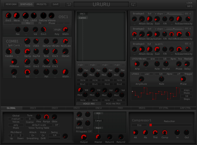
By Simon LangfordThere are countless reverbs, EQs and delay‑based effects out there, but U‑he's new Uhbik collection brings some fresh thinking to familiar sounds.With a name derived from a Philip K Dick novel, the Uhbik suite of plug‑ins from u‑He aims to combine a simple parameter set with some less common features and a vintage look. The suite is available in VST format for Mac OS X and Windows, and in Mac Audio Units format. Eight plug‑ins form the initial release, and all owners are guaranteed free updates to all of these plug‑ins, as well as free downloads of any future Uhbik plug‑ins developed. The first of the scheduled new plug‑ins will be Uhbik‑X, a 'virtual rack' in which to load individual Uhbik plug‑ins to combine them.A single ZIP file of about 17MB contains all the plug‑ins (you cannot selectively install individual plug‑ins) and installs very easily.
- U He Diva Modules
- U He Ace Keygen Mac Os Download
Information about the torrent U he Diva v1 3 1 AU AAX VST VST3 OS X DOA packet dada dmg. If you want to download the torrent U he Diva v1 3 1 AU AAX VST VST3 OS X. U-he Diva free download. Mulperi Sound Vol 1 for u-he DIVA - Duration: 16:28. U-he.Uhbik.VST.v1.0.Incl.Keygen-AiR U-he.Uhbik.VST.AU.v1.0. Feel free to post your U-he Uhbik VST v1.0. Master PDF Editor 5.4.38 Crack 2019 Serial Key Linux + MAC OS X Keygen Full Version. Master PDF Editor Crack is a nice piece of software that is very useful relevant to work with PDF files. Furthermore, you can do a lot of work using its very powerful features. In addition, it allows the PDF people to carry out many useful tasks on the PDF document.
Once installed, the only limitations are vinyl‑like crackles that occur every now and then after two minutes of use. To authorise the plug‑ins, you simply enter a user name and authorisation code that are provided upon purchase to remove these crackles.Uhbik‑A is a purely algorithmic reverb, which is actually a pleasant change from the current glut of convolution reverb plug‑ins.
Even when the latter give you the choice of a wide range of 'real' acoustic environments, sometimes an algorithmic reverb just seems to feel better for some tasks.Uhbik‑A works by combining early reflections with a plate‑like algorithm to give a unique sound. The parameters available are relatively self‑explanatory, with all of the usual control that you would expect from a reverb, and three modes of operation. The manual describes these as follows: 'Open is probably the best choice for subtle ambience, while the direct model may be more suitable when used up‑front. Small is predestined for smaller rooms with prominent early reflections and a relatively short tail.” Rather than being simple tone controls, the bass and treble parameters set the relative decay times of the bass and treble frequencies of the reverb signal.In use, Uhbik‑A can sound very varied, as a quick run through the included presets will show you. It can do everything from muted ambiences and bright, lively rooms, through to pseudo‑doubling effects ('Opener' is a nice example of this) and on to those shimmering and glossy reverbs that seem to make vocals drift on forever (have a listen to 'Snow Dome' to illustrate this).
I tested Uhbik‑A on a variety of sources, from percussive sounds and vocals through to acoustic and electric guitars, and even big and lush synth pads. The one thing that really stood out for me was how well the resulting sounds blended into a mix. The reverb managed to give the sounds an added third dimension without actually detracting from the source sound and, in this respect, Uhbik‑A achieves exactly what it sets out to.
When you listen to the sounds in isolation, they might not sound like real acoustic environments, but when you hear them in context, they really do come to life, in a subtle and characterful way.I do have a couple of complaints, though. The first is that some of the presets are a little heavy‑handed, something which is also true of the other plug‑ins in the suite.
I expect they were set up in this way to really demonstrate what the plug‑in is capable of when taken to extremes, and they do, but manual tweaking of the parameters may be needed to achieve results that work in your mix. The second, and perhaps more serious complaint is that some of the controls glitch when you apply very fast and large parameter changes. The worst culprit for this is the pre‑delay control which, when changed from minimum to maximum quickly while a signal is being processed, emits a buzzy noise for a split second.
To be fair, this probably isn't something that you would do on a regular basis anyway, but it is something that needs looking at nonetheless, and fixing in a future update.Uhbik‑D is a multi‑tap delay unit with five separately controllable delay taps. The controls for each are identical and feature a duration that is set in 16th notes, up to a maximum delay time of one bar, plus a pan control and a volume control.
Other controls help simulate the fluctuations inherent in old‑fashioned tape delay, so as well as the normal wet/dry mix and basic tone controls, there are feedback, soft clip and modulation controls, the last of which aim to simulate the wow and flutter of an old tape‑based unit.The relationship between the delay taps and the feedback confused me at first. I set up the first tap with a delay time of 4/16ths and, as expected, I got a one‑beat delay. Next I wanted to add some feedback, so I turned up the feedback control but ended up getting an 8/16th time for the feedback.
It took me a little while to realise that the feedback time is set by clicking on the feedback buttons at the bottom of each tap. If the light is illuminated, it means a feedback time as set by the delay time of that tap is activated. The mistake I had made was having the feedback of a different tap activated! Activating the feedback control on the correct tap soon solved the problem. The slightly unintuitive down side of this is compensated for by the fact that you can have multiple different feedback times but, sadly, each of these is applied to the entire wet output, rather than each tap having a dedicated feedback time.The rest of the controls work as you would expect and do a good job of emulating the sometimes wobbly nature of tape delays. The one thing that I did notice was a slightly metallic tone to the delayed signal, unless there was some judicious use of the filters provided to slightly damp the delayed sound.Uhbik‑F mimics both classic 'through zero' tape flanging and the stomp-box‑style alternative, which uses very short delays and feedback systems to create comb filtering. The heart of any flanger is the actual movement of the effect, as controlled by an LFO, and the range of options in Uhbik‑F goes much further than the typical speed, depth, waveform and phase controls.
Here, the speed control can be set in a variety of units, including quarter notes, 1/x notes (where a value of x=8 would give an eighth‑note cycle, a value of 16 a 16th‑note cycle, and so on), seconds, Hertz and 'manual'. Most of these made sense, but I could not, either through looking in the PDF documentation or by experimentation, actually work out what the manual setting did! There are also a lot of options for controlling the shape of the LFO: controls for scale, wave and symmetry go far beyond what you would expect, and actually provide many possibilities for creative and rhythmic flanging effects.The actual sound is top‑notch, and with the inclusion of both types of flanging, you can create almost any effect that you could want, from smooth and oh‑so‑subtle, to in‑your‑face sounds that are just dying for a chance to blow your tweeters. And, of course, given that stomp-box flangers and chorus effects are closely related, it is also possible to set up some quite nice chorus settings here as well, although personally I think that's a perk rather than a purpose.Uhbik‑P shares a lot of the same modulation topology, but the actual parameter set is a little different; there are controls for the wet/dry mix, the depth of the effect, the centre frequency of the effect and positive or negative feedback amount. Finally, there is a switch that controls the number of stages which, unusually for a phaser, starts at 14 and goes all the way up to a stratospheric 42! For those of you unfamiliar with phasers, the number of stages (technically, all‑pass filters) involved will directly influence the apparent depth and 'swirl' of the phaser.Browsing through the presets, I was surprised at just how resonant the 42‑stage phaser could be! In many cases, this phaser can take on the qualities of a resonator and give you all manner of 'tuned pipe' sounds; as was the case with the reverb, some of the presets are actually a little distracting, as I feel that most users wouldn't use these kinds of extreme settings too often.
I actually got results which were much more usable, to my ears, with the 14‑stage and occasionally the 28‑stage settings, but kudos to designer Urs Heckmann for including the 42‑stage option! In general, the sound is quite spacious, open and airy, and even 'chewy' (don't you just love the language we all speak in relation to sound?). The overall character didn't strike me as being as 'different' as that of the other plug‑ins here, but it's still a very useable example of a phaser.Uhbik‑Q is a three‑band equaliser with low‑ and high‑cut filters as well as an overall gain control. The first of the three bands is a low shelving EQ, with a choice of six corner frequencies and a boost/cut range of ±24dB. The remaining two bands can be switched between 'low shelf', 'wide bell', 'flex bell', 'narrow bell' and 'hi shelf' modes.
U He Diva Modules
'Flex bell' is a variable‑Q system where the bandwidth of the cut or boost narrows progressively as the cut or boost is increased. The effect of this is to somewhat limit apparent overall volume changes when using extreme gain settings.So far what we have is a pretty standard, albeit very flexible EQ, but the gain control offers something a little different. It can function as an overall output level control, but there are two other options: wide mids and centre bell. With either of these two options enabled the gain control becomes, in effect, an extra tone control, with the wide mids offering a very wide mid‑range cut/boost and the centre bell offering something similar to the flex bell settings on the other bands. I am not sure why this option wasn't offered as a separate band in its own right, but it is a valuable inclusion nonetheless.Everybody has different tastes in EQ, but I think that this EQ would make a valuable addition to any collection. It can offer some very serious shelving cuts useful for isolating certain parts of sounds, but it also lets you make gentler, broad‑spectrum adjustments.
For me, one of the nicest applications was when I put the EQ across the master bus and used the low‑frequency control, set at 90Hz, to boost the bottom end of a mix that I was working on. The result was warm and rounded without sounding overdone and digital.
U He Ace Keygen Mac Os Download
Trying a similar thing with a boost on the top end seemed a little more obvious and less controlled, but still usable with careful adjustment. I personally preferred the sound when it wasn't pushed too hard: for me, the mid and high boosts were just a little on the brittle side, though certainly no worse than many of the other EQs that I use regularly.Uhbik‑S is a bit of a strange beast. It isn't exactly a ring modulator, though it can be made to sound like one. It isn't a phaser, but, again, it can be made to sound like one. It is both of these and neither, and an awful lot more besides!The principle behind it is simple: it applies a fixed frequency shift to any signal. The effect is that different input frequencies seem to be shifted by different amounts. If the shift was set to 100Hz and you had a 100Hz sine-wave input, the result would be 200Hz, an octave higher.
But with a 400Hz sine wave the output would be 500Hz, which is definitely not an octave higher. This can lead to seemingly inharmonic and metallic results with larger shift intervals, but also chorus and phaser‑like results when used with very small shifts.In fact, it was this application that I preferred in the end. With some experimentation, I was able to produce some absolutely gorgeous phasing effects that sounded remarkably similar to the swirling pad sounds of Jean Michel Jarre's Oxygene album. One thing I soon noticed was that when using Uhbik‑S to generate phaser‑like sounds, the phasing effect is more like a 'barber pole' effect, where the phaser seems to be constantly sweeping upwards (or downwards) rather than having an obvious LFO‑driven modulation.
This is actually a really pleasant effect and, in my mind, preferably to the cyclic phasing effects that are more common. Using some of the more ring modulator‑like settings on vocals produced a dizzying array of scary vocal tones that I am sure will end up giving me nightmares at some point! These kinds of effects have never really been to my taste, but when I tried them on some sampled drum and percussion loops they really came to life. They can give anything from a real lo‑fi edge to strange tuned overtones, and sometimes even bring out pitches in loops that I didn't even realise were there, turning a purely percussive loop into a melodic one. Very useful!Uhbik‑T goes far beyond familiar tremolo effects. In place of the usual LFO, you can use a sequencer with up to 16 steps to trigger patterns of modulation (below).OK, this is where things really start to get interesting!
Uhbik‑T is described as a 'trans‑modern pan and tremolo” but, in my opinion, that description doesn't even begin to do justice to what this plug‑in is capable of. In fact, I think that a full description of all it can do would probably take longer than this whole review, so I would refer you to the excellent manual for a full description of what is possible. But, in a nutshell, you get traditional amplitude‑based tremolo effects, along with a low‑pass filter that is modulated by the same LFO but with an independent depth control, plus a Haas delay, again controlled from the LFO and with its own depth control. So you can actually combine the three different effects in any combination or levels. The Haas delay applies a very short delay between the two channels that isn't heard as a discrete echo, but gives us the effect of direction and helps us place sounds in a three‑dimensional space.In use, I found the amplitude and filter sections worked as expected, but whereas the Haas delay section gave a sense of spatial movement on percussive sources, it seemed to function more like pitch modulation on melodic sources. The real fun starts when you abandon the LFO in favour of the pattern generator.
This is, in many ways, similar to the step sequencers found on some analogue synths. For each of up to 16 steps you can set a modulation depth between 0 to 100 (in multiples of 10), with results ranging from stepped waveforms to more 'trance gate'‑like effects.
In addition, you can have up to 11 different patterns to choose from, with the option to use different ones on each channel and the ability to smoothly crossfade between patterns. Impressive stuff for sure, and the only thing I missed was the ability to combine cyclic LFO modulation and the pattern sequencer, so you could have a 'gated' pattern that was also swept up and down by the LFO — but now I'm just being fussy!Rounding out the package is U‑He's take on a filter.
To me, though, Runciter is much more than just a filter. To start with, it offers simultaneous low‑, high‑ and band‑pass modes, an envelope follower with adjustable response time, and a wet/dry mix control which, while not unique, is certainly unusual for a filter plug‑in. The filter's resonance control ranges from the subtle to the downright rude (watch those tweeters) and is joined by fuzz and drive controls, each providing a different kind of distortion. The fuzz is an unashamedly nasty piece of work, while the drive algorithm sounds a little more polite! As far as I could tell, with all the filter controls set to have no effect, the drive control actually needs to be set at ‑48dB to have no effect, which is a little counter‑intuitive to me. At 0dB there is a noticeable amount of drive, which I wouldn't expect with all the filter controls set in 'neutral' positions. Once again, as with a few of the other quirks of these plug‑ins, it isn't a problem as long as you remember what is going on.As a straight‑up filter, Runciter sounds perfectly good.
I think that the resonance maybe goes a little too far or, at the very least, the resonance control itself could have a little more bias towards the lower end of the range, as you can get up into self‑oscillation pretty early on. You could choose to ignore the filtering altogether and just use the fuzz and drive sections as a distortion effect and, again, it works very well (albeit with limited controls). However, the real fun, and I guess purpose, of Runciter is to create some absolutely filthy distorted effects that sound like you are playing a busted‑up old synth through a tiny guitar practice amp with a speaker cone that has a big tear in it. There are quite a few good filter plug‑ins out there, but I cannot honestly think of one that does dirty quite so well!In the time I have been using these plug‑ins, I have got used to their sometimes quirky nature, but it can be off‑putting to start with. Some people may view it as a negative point that control ranges are simply numeric, instead of having actual frequency values, but I actually think it is a positive thing. After all, when we are adjusting the frequency of an EQ band, we should be listening rather than looking at numbers!I don't do surround work myself, but the design of these plug‑ins makes possible some interesting three‑dimensional effects, as key parameters such as the phase offset on LFOs and delay tap panning work in surround.As I mentioned earlier, the presets are a bit on the extreme side, but they do at least show what the units are capable of. At first sight, a collection consisting of a reverb, delay, flanger, phaser, EQ, tremolo, frequency shifter and filter might not seem that interesting.
But I honestly think that Uhbik is worth a serious look, because even though the basic units are not new effects, their implementations here give us something at least a little different in each case, and very different in some cases! They represent very good value and will be a welcome new addition to my Mac. Will they become ubiquitous? (Sorry, I couldn't resist!) That I don't know, but they definitely deserve to be checked out. All contents copyright © SOS Publications Group and/or its licensors, 1985-2019. All rights reserved.The contents of this article are subject to worldwide copyright protection and reproduction in whole or part, whether mechanical or electronic, is expressly forbidden without the prior written consent of the Publishers.
Great care has been taken to ensure accuracy in the preparation of this article but neither Sound On Sound Limited nor the publishers can be held responsible for its contents. The views expressed are those of the contributors and not necessarily those of the publishers.Web site designed & maintained by PB Associates & SOS.
torontosite
Источник: [https://torrent-igruha.org/3551-portal.html]u-he Uhbik - Effects Bundle (Serial Download)
Digital Downloads (buying software)
All software marked as "serial download" or "digital download" will be delivered via email within normal office hours.
Simply add the software to the basket and at the delivery stage in the checkout please select "Digital Download - Software by email" as your delivery method
Delivery Charges (Main Products)
All orders over £39.00 will be delivered free via our standard delivery 2-3 days (UK Mainland)
If you need your item faster we also offer a Priority Tracked service at £3.99 (1-2 days) or Next Day Tracked £6.99
(please ensure you add a mobile number to your order for tracking)
Saturday delivery is available when ordered before 2pm (Mon-Fri)
All orders below £39.00 will start as low as £2.99 depending upon weight and qty(s) (UK Mainland)
All Delivery options will be available at the delivery stage in the checkout
EU Delivery Times
Non UK Mainland Addresses please allow 1-3 Days
Delivery To Belgium / France / Germany please allow 3-4 Days
Music PC Systems - Please allow 5-7 Working Days build time (UK) 7-14 (Rest of the World)
French - Pour la Livraison s'il vous plaît permet en France 2-4 Jours
German - Für Lieferung Nach Deutschland erlaubt bitte 2-4 Tage
Delivery Notes
On delivery you must inspect the goods carefully for damage as Inta Audio is unable to accept responsibility for damage in transit, shortage of delivery or loss of products unless the customer advises Inta Audio of such within three working days from the date of delivery.
Returns Policy
We ask that you follow these guidelines to help us process your return as quickly and efficiently as possible:
1. Please keep your order reference to hand. This confirms your original order and gives us the necessary details to authorise the product’s return.
2. Contact our Customer Services Team on 02476 369898 (or e-mail cs@inta-audio.com). We will then send you an RMA number and returns form which needs to be completed and sent back with the returned item(s).
3. (If the order has been unpacked) re-package it to ensure that it is being returned in its original condition. Please make sure all items relating to the product are returned, including manuals and cables.
4. When returning an item please obtain a ‘proof of postage’ receipt from the Courier.
Returned items must be mailed within 10 days of when the RMA Number has been issued. Items received with a post date 30 days after your requested return will NOT be eligible for refund.
Please note: Our returns policy is quite straightforward but there are a number of conditions that we ask our customers to comply with before applying:
1. It is your responsibility to request a return. If you don’t tell us you want to make a return, we don’t know. Once you do tell us, we will do everything we can to action it.
2. If you have not requested a return within 28 days of receiving an order, we will have assumed that you are intending to keep it and we will not authorise a return.
3. We always refund the payment according to how the original purchase was made and aim to do so within 72hrs of the return being received by us.
4. Returned goods are liable for a restocking fee of 15% towards handling and repackaging if the order is not returned in its original, unopened packaging. This charge will be subject to our inspection of the returned goods.
5. Delivery charges will not be refunded unless the delivered goods are faulty.
6. Replacement products are dispatched immediately after the returned goods have been received and accepted by Inta Audio.
7. Items that develop a fault within 30 days of delivery are eligible for a replacement or a refund. Delivery costs are also reimbursed for faulty items. Please contact our Customer Services Team on 02476 369898 if you believe your item has developed a fault.
Finally, please remember that notifying us of your intention to apply for a return, saving the delivery paperwork and keeping the order in its original packaging will help both you and Inta Audio to process the return quickly.
If you have any questions about our Returns policy please telephone us on 02476 369898 or email us at cs@inta-audio.com.
lookhead’s blog

7 OPTICODEC PC Remote Introduction Description Note Information Connection to Unit The OC PC Remote software is a 32-bit version for Microsoft Windows 98/2k/ME/XP for the remote control of the OPTI- CODEC over the RS232 interface using a PC. It covers the same adjustment parameters as the OPTICODEC itself. To avoid any misunderstanding, the OPTICODEC PC Remote is referred to on the following pages as OC Remote or OC Remote software. The licensee may not copy the software or the included original documentation or own any such copies. Furthermore, the licensee may not change, adapt, translate, duplicate, loan, lease or in any other form supply the availability of the software or service instructions as a whole or any part thereof. It is strictly forbidden to reengineer or disassemble the software, or in any other way and means attempt to trace the source code.
Due to the further development for product improvement of the present series units and alterations of certain industrial parts, it cannot be avoided that some parts might not be fully compatible. Different component modifications can lead to different configuration options. Deviating program sections in the software are therefore possible. All technical information may be subject to change without notice.
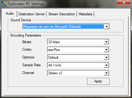
Please visit the main page of Opticodec-PC LE on Software Informer. Share your experience: Write a review about this program Read more. Info updated on: Sep 07, 2018. Related stories. Best Black Friday deals on PC games. 5 best classic PC games of the 90s. Comments 0 comments. Notify me of replies from other users. Orban Opticodec-PC. Download Link. Encoder for HE-AAC/aacPlus v2. To download the above app search for Chiqui Pop on Apple Store and Google Play.
The connection between the PC and your OPTICODEC occurs via a serial 9-pole cable (KB003 male/female). Connected to PC Connected to OPTICODEC In addition, a 9/25-pin adapter (OC7600 adapter.) is required.only for OPTICODEC 7600, not for other models. OPTICODEC PC Remote E 7. 8 Software Installation Download of the OC Remote Software Start the setup program of the current application from the Internet or from the delivered data medium with a doubleclick on the setup icon.
Follow the installation instructions on the PC screen. With double click on the icon you start the application. After a short initializing sequence the basic configuration menu of the connected OPTICODEC appears. Program Configuration A mouse click on the 'Program' menu opens a pulldown menu.
This configuration is only necessary if TIMEOUT! Is displayed and not STANDBY. With the menu item Program Configuration you can adapt the PC serial interface and adjust the display colors. A safety query to appear before a connection is disconnected can be set up by activating the Confirm disconnect check box. Via 'Default Input' you can select the audio input by using of the Direct Dial Buttons. You can choose between: Analog, AES/EBU and S/PDIF. Confirm yor settings with OK.
8 E OPTICODEC PC Remote. 9 Software Info Release of Additional Features The menu item 'Enter key codes' is used for release of additional features (e.g. The 4SB ADPCM algorithm). The release is dependent on the unit model and its serial number.
Each unit receives a unique key code. This function is only active in the standby mode. About OC Remote A window is displayed over the next menu item called About OC Remote where you will find information on the version number, creation date and manufacturer of the OC Remote software.
Info This function is found on the 'Unit/Info' pulldown menu and serves to display the latest software versions of the connected OPTICODEC unit. All software parts with their corresponding versions are displayed. You can also interrogate the serial number of your OPTICODEC. OPTICODEC PC Remote E 9 10 Software Update Software Update This function is found on the 'Unit/Software Update' pulldown menu.
Any new software updates can be downloaded free of charge at any time from the ORBAN Europe Internet server ( or from the supplied data media. If necessary, please store the device-specific.BIN file on your local hard drive under Program Files/Orban/OpticodecRemote/Updates. The program automatically recognizes the connected OPTICODEC and which software parts are to be updated. A dialogbox accompanies you throughout the update and informs you about the current process 10 E OPTICODEC PC Remote 11 Software Update The OPTICODEC 7600 shows the update process in the display. Warning Do not switch off your PC or OPTICODEC during the update process. Damaged or incompletely loaded software always causes an error message.
After a failed update, you may repeat the update process. Turn the unit off and then back on again.
If a software update is cancelled during the programming operation, the unit may not start and/or may display only the company logo. If this happens, the unit can be revived only by its manufacturer, ORBAN Europe GmbH in Ludwigsburg. OPTICODEC PC Remote E 11 12 Data Input Data Input In standby mode select Data Input from the main menu or alternatively the 'Data/Edit local directory' pulldown menu.
The telephone directory appears (ISDN/IP Directory). The window and columns widths are variable and can be modified with the mouse.
Creating a New Recipient Open the input mask by clicking onto the function New. Here you have the choice between ISDN or Ethernet. 12 E OPTICODEC PC Remote. 13 Data Input ISDN Connection Depending on the number of installed ISDN modules, the writeable input fields are represented white. Two B-channels are available for each ISDN module.
Activate an input using the mouse. The positioning marker of the cursor blinks when the number can be entered. Move between ISDN input fields using the tab key. Once the ISDN numbers have been entered, you can assign a name to the recipient (max. 49 characters). Edit Recipient The ISDN/IP address directories of the connected ORBAN OPTICODEC 7600, OC 7400, CTAXI or PAN-PRO can easily be imported and exported via the 'Data' menu to your PC for more efficient management. Select the entry you want to process from the ISDN/IP directory using the 'Edit' key or with a mouse double-click.
To delete a recipient click with the left mouse button onto the entry in the ISDN/IP directory you would like to delete and press the 'Delete' key. Deletion takes place after confirming with the OK key. Alterations of the default audio configuration can be made by clicking onto the Change key. The configuration menu of the audio parameters which are assigned to the current entry appears. By activating the arrows (left-right) you can change the pre-settings.
OPTICODEC PC Remote E 13 14 Data Input Algorithm The 'Algorithm' menu item is used for presetting the desired data reduction procedure on outgoing calls. By pressing the arrow keys, you can select between Layer 2, Layer 3, G.722, G.711 and 4SB ADPCM (optional). ISDN Sync The 'ISDN Sync' menu item is used to set the desired synchronisation procedure of the partner codec. The available sync modes for Layer 3 are: AUTO automatic codec detection MusicTAXI (MusicTAXI sync for 1 to 6 B-channels) NO SYNC for the use of 1 x B-channel NO SYNC (INV) for the use of 1 x B-channel ZEPHYR (Telos sync for 2 B-channels) For Layer 2: AUTO automatic codec detection. MusicTAXI (MusicTAXI sync for 1 to 6 B-channels) NO SYNC for the use of 1 x B-channel NO SYNC (INV) for the use of 1 x B-channel PRIMA (CCS sync for 2 B-channels) AETA (for 4SB ADPCM; optional) The activation for AETA sync and 4SB ADPCM algorithm (not included in the standard delivery) is performed as described on the page #9.
Bitrate According to the setting of the algorithm and the number of outgoing B-channels, the transfer rate is set here: 64, 128, 192, 256, 320 or 384 kbps for layer 2 and 64, 128, 192, 256 and 320 kbps for Layer E OPTICODEC PC Remote 15 Data Input Samplingrate Audio Mode The 'Samplingrate' menu item is used for setting the desired sampling frequency on outgoing calls. You can choose between: 16, 22.05, 24, 32, 44.1, 48 khz, AUTO (the sampling frequency of the addressing device is used) The 'Audio Mode' menu item is used for setting the desired audio behaviour on outgoing calls.
Mono Dual Mono Stereo Joint Stereo mono signal. The left input is used. Two different signals which do not jam each other, e.g. Left channel: original soundtrack; right channel: translation as for Dual Mono, each channel is encoded separately, but with the difference that a channel is allocated excess bits if less or no audio is transmitted on the other channel (i.e. Bit distribution as needed).
Comparable with MS stereophony (middle/ side signal). Encodes the sum between left and right and the difference between left and right; these are encoded and transmitted separately (subjectively better quality at low data rates). Audio Input Userdata Note The 'Audio Input' menu item is used for setting the desired audio input on outgoing calls. You can choose between: Analog and AES/EBU and S/PDIF.
The menu item 'Userdata' is used for setting the desired ancillary data on outgoing calls. You can choose between: OFF (no ancillary data is transferred) 1200, 2400, 4800 baud with Layer 2 and 3. If the ancillary data is switched off (OFF), no remote effect signals are transmitted either. Between OPTICODECs, the smallest preset baud rate of the ancillary data is used in the context of the device handshake.
OPTICODEC PC Remote E 15. 16 Data Input G.722 Connection with H.221 or SRT Sync If you enter a G.722 partner in the Data Input menu, please observe the following order: 1. Enter the ISDN number.
Enter G.722 in Algorithm 3. Determine the Sync modes in ISDN Sync. Now H=H.221 or S=SRT is displayed in the directory for the selected SYNChronisation procedure.
X.21 Connection Codec Loop To activate the X.21 interface, enter an 'X' in the ISDN field (e. Position #11 in directory). If the input fields are empty, the OPTICODEC starts the codec loop mode. This serves as a test for the coded audio signal (without ISDN). Position #12.) 16 E OPTICODEC PC Remote 17 Data Input Ethernet Connection Should an Ethernet connection be desired, please activate the radio button for Ethernet. Enter the target address and, for easier identification, also enter the name of your connection partner.
You may enter both IP address and plain-text names. (.
Only if a name server also exists.) Audio Configuration In the same way as the description of ISDN connections, you can set the audio parameters for the planned connection here. The menu guides you through algorithm (Layer 2 and Layer 3), mode, bitrate, and finally userdata. Mode To transfer audio signals in real time over IP networks (VoIP = Voice over IP), three protocols are used: Point-to-Point A bi-directional connection between two units. TCP is utilised as the protocol, possible transmission errors are corrected to a certain degree by this protocol. These entries are marked with an 'x' in the Sync column of the directory (e. #11, on page #18). SIP/RTP SIP (Session Initiation Protocol) Signalling protocol responsible for the establishment, termination and control of connections and RTP (Real-time Transport Protocol).
The actual voice connection is created using data units (streams) by means of RTP. These entries are marked with an 'n' in the Sync column of the directory (e. #12, page #18). RTP RTP is special protocol for the transmission of realtime data (here for audio signals) and uses UDP (User Data Protocol) as transport protocol. These entries are marked with an 'r' in the Sync column of the directory (e.
#12, page #18). OPTICODEC PC Remote E 17. 18 Data Input Tip The local ISDN/IP directory is saved in the OpticodecRemote program directory as a num.dat file. This directory can be easily exported to any number of PCs, hence saving time by copying the same address book directory to all of them. Saving the Unit ISDN/IP Directory to your PC Harddisk Use the feature Save directory to disk to store the ISDN/IP directory of your unit on PC.
Do this by selecting the file format you require, either Directory File (.DIR), Text separated Files (.TXT) or Comma separated Files (.CSV) and importing the address book into MS Word or Excel, for example. These file formats can also be exported to the unit. However, the program s own editor can run only.DIR file formats. 18 E OPTICODEC PC Remote. 19 Data Input Edit saved directory The entries can be edited, newly entered, deleted and sorted by means of the Edit saved directory function. Double-click a vacant field of entry in the directory to enter a new codec partner Loading ISDN/IP Directory to a Unit Click onto Load directory to unit, locate the desired.DIR file and finally activate the Open key.
All 96 entries (connection partners) with their names, ISDN numbers/ip addresses and set audio parameters are now loaded to the unit. It is irrelevant whether all or only some of the entries have been occupied or whether they are all or partly vacant; or whether the connected unit is an OPTICODEC 7600, OC 7400, CTAXI or PAN-PRO. Exporting the directory can easily be repeated should it fail because of for e.g. A power down or power failure. OPTICODEC PC Remote E 19.
20 System Setup Configuration of the connected OPTICODEC in System Setup Select 'System Setup' from the 'Unit' pulldown menu. The basic configuration menu of the connected OPTICODEC differs in appearance depending on the unit type and its equipment. TCP/IP Basics Init Mode In this menu item the basic settings of the unit within the network are entered. With this menu item, you set the initialization mode of the OPTICODEC. You can choose between: Manual DHCP Disabled Manual setup of your IP address Dynamic Host Configuration Protocol (DHCP) permits, with the aid of a corresponding server, the dynamic allocation of an IP address and additional configuration parameters in a TCP/IP network (e.g. Internet or LAN) Network interface deactivated. Warning Local IP Address Subnet Mask If the functions DHCP or Disabled are activated, all additional submenus are disabled.
In the data entry mask, enter the IP address of your OPTICODEC. Be aware that every connection to the network must possess its own unique IP address. The 'Subnet Mask' is used to subdivide a network into smaller subnets, in order to reduce the data traffic to the subnets and/or permit better administration of the data traffic. 20 E OPTICODEC PC Remote. 21 System Setup Default Gateway The data exchange occurs between the various nodes in the network with complete transparency to the user. However, the IP software detects when a data packet is intended for a different subnet and sends it to the corresponding gateway. If necessary, you can enter the IP address of a router here.
Otherwise, must be entered. Note You will be informed of the IP address, Subnet Mask and Default Gateway by your network administrator. Name Server Domain Name Servers (DNS), also called name servers for short, are responsible for the conversion of Internet hostnames into Internet addresses, since the actual communication in TCP/IP networks is based on IP addresses. Enter the IP address of your DNS here. If DHCP is activated, this menu item is disabled or the settings are taken from the DHCP server.
Domain Name Enter the name of your domain here. If DHCP is activated, this menu item is disabled or the settings are taken from the DHCP server and the OPTICO- DEC can be addressed via 'Unitname.Domainname. OPTICODEC PC Remote E 21 22 System Setup TCP/IP Audio The settings for audio transmission over the network are found in this menu. Buffer Management This buffer is used to bridge short interruptions in the data transfer. The size of the buffer (which temporarily holds the data from the network) can be influenced.
To ensure the most secure transfer possible, the maximum value (bar all the way to the right) should be set; however, this results in a longer delay. If more value is placed on having a shorter delay, then the bar can be moved to the left; however, this has a negative impact on the transmission security. To permit the best possible transmission security with a short delay, you should ensure that no additional devices/ workstations apart from the OPTICODEC are transmitting data over the network. Quality of Service Not all applications have equal status for data transfers, and not all applications require the same high standards for data transfers. To minimise or prevent the risk of bottlenecks in data networks, the IP header implements the so-called 'Quality of Service (QoS) in addition to the identifier fields such as time to live, protocol and header checksum.
If the router is configured accordingly, QoS actively regulates the load status on the network and uses the available bandwidth intelligently and effectively on the basis of data prioritisation or bandwidth reservation. 22 E OPTICODEC PC Remote 23 System Setup Type TOS Precedence Values TOS (Type of Service) or DiffServ (Differentiated Service Architecture) are key mechanisms of QoS and are responsible for determining the packet priority. The TOS bits contain information about how a data packet should be handled by a router. For example, an overloaded router can determine, by means of the TOS field, which packets are less important (and can therefore be dropped) and which packets must absolutely be transmitted. Precedence Significance Precedence Significance 000 Normal 011 Flash 010 Priority 100 Flash Override 010 Immediate 101 Critical TOS Values TOS Significance TOS Significance 0000 Normal 0010 max. Reliability 1000 min. Delay 0001 min.
Monetary Cost 0100 max. Throughtput DiffServ DiffServ uses a new definition of the IPv4 TOS header field and IPv6 traffic class header field. The goal of DiffServ is to subdivide the data traffic into service classes with different priorities, without using the intensive signalling on each router.
Each packet can be marked and is handled and transmitted accorded to this marking. DiffServ Codepoints (DSCP) Note Each per-hop-behaviour (PHB) flow is determined by a DSCP. You can choose between: Standard (Default, 'Best Effort'), Class Selector 1-7, Assured Forwarding 11-13, 21-23, 31-33, 41-43, and Expedited Forwarding. Details and additional specifications can be found in the generally available Request for Comments lists (RFC1349 TOS; RFC2474 DiffServ) on the Internet ( OPTICODEC PC Remote E 23.
24 System Setup Audio Data Encoder This encoder configuration is taken over when the OPTI- CODEC is called by another OPTICODEC over IP. The pre-settings are AUTO. Descriptions of the individual functions can be found on pages Audio Port (TCP) This menu contains the setting for audio transfer over the network with TCP protocol. The setting is for pointto-point. For the OPTICODEC, the value 6136 should always be entered.
Audio Port (RTP) Here you enter the port number for the audio transfer over RTP. The settings are for SIP/RTP and RTP. For the OPTICODEC, the value 5004 should always be entered.
In the basic settings, this value is used by default. For the audio transfer, two port numbers are used - the one entered here and the port number immediately above it. Note When using other port numbers, please be aware that the lower of the two numbers must be entered and must be an even number. 24 E OPTICODEC PC Remote 25 System Setup TCP/IP Remote Control Unit Name Port Accept Configuration For easier identification of devices on the network, the name of your OPTICODEC must be entered here without name length restrictions. This name is transmitted to the 'NETControl' program and shown in the device list.

Here you enter the port number for remote control over the network. For the OPTICODEC, the value 6137 should always be entered. This point determines the call accept mode of the OPTICO- DEC. You can set the accept mode more or less specific for the unit and transmission permanently. Then the OPTICODEC only accepts calls in the respective configuration.
Or you can select the operation mode AUTO(matic Codec Detection). The OPTICODEC serves as a SLAVE and takes over the parameters of the calling unit automatically. The AUTO mode is not available for Audio Input and Userdata.
OPTICODEC PC Remote E 25. 26 System Setup Algorithm The 'Algorithm' menu item serves for setting the desired data reduction procedure on incoming ISDN calls. You can select between: Layer 2 Layer 3, 4SB ADPCM (optional), AUTO (G.711/G.722 calls are also accepted). Please see also Brief Lexicon, page #47. ISDN Sync The 'ISDN Sync' menu serves for setting the desired synchronization procedure. You can select between: MusicTAXI (MusicTAXI Sync for 1 to 6 B-channels) PRIMA (CCS Sync for 2 B-channels) ZEPHYR (Telos Sync for 2 B-channels) AETA (for the 4SB ADPCM algorithm; optional) NO SYNC when using 1 B-channel NO SYNC (INV) when using 1 B-channel AUTO - Automatic Audio Codec Detection Note Bitrate Samplingrate If a sync other than MusicTAXI or AUTO is preset, G.722 calls can not be received. The menu item 'Bitrate' cannot be adjusted.
The transmission rate is determined and set according to the number of incoming B-channels (always 'AUTO'). The Samplingrate menu item serves for setting the desired sampling frequency when calls are coming in. You can select between: 16, 22.05, 24, 32, 44.1, 48 khz AUTO (the sampling frequency of the calling unit is taken over).
26 E OPTICODEC PC Remote 27 System Setup Audio Mode The 'Audio Mode' menu item is used for setting the desired audio behaviour on outgoing calls. Mono Dual Mono Stereo Joint Stereo and AUTO mono signal. The left input is used. Two different signals which do not jam each other, e.g. Left channel: original soundtrack; right channel: translation as for Dual Mono, each channel is encoded separately, but with the difference that a channel is allocated excess bits if less or no audio is transmitted on the other channel (i.e. Bit distribution as needed).
Comparable with MS stereophony (middle/ side signal). Encodes the sum between left and right and the difference between left and right; these are encoded and transmitted separately (subjectively better quality at low data rates). The audio mode of the calling unit is taken over. Audio Input Userdata Note The menu item 'Audio Input' serves for setting the desired audio input, when calls are coming in. You can select between: Analog, AES/EBU and S/PDIF. The menu item 'Userdata' serves for setting the desired ancillary data, when calls are coming in.
You can select between: OFF (no ancillary data is transmitted) 1200, 2400, 4800 baud in Layer, 2400, 4800, 9600 baud in Layer 3. If the ancillary data is switched off (OFF), the alarm control signals are also not transmitted.
From OPTICODEC to OPTICODEC, the lowest preset baud rate of the ancillary data is agreed within the unit handshake. Press OK (left mouse click) to take over the presetting of the call acceptance. Press Cancel and the presetting is not taken over.
OPTICODEC PC Remote E 27. 28 System Setup ISDN Configuration ISDN Protocol The OPTICODEC 7600 is equipped by default with a Stollmann type ISDN module and the following ISDN D- channel protocols: EURO (DSS1), NATIONAL 1/2 (North America), JATE (Japan), AT&T (USA), VNx (France) and AUSTEL (Australia). For use in the USA, the OPTICODEC 7600 can be equipped with 'IMD4 type ISDN modules. This is necessary if additional U-interfaces are required for North America. When 'IMD4 modules are used, the device possesses two ISDN D-channel protocols: EURO (DSS1) and NATIONAL 1 (North America). Achtung Accept Telephone Calls Decisive is the ISDN protocol of your connection, not the one of the partner unit! You can alter the settings by pressing the arrow keys.
This menu item serves to define the OPTICODEC behavior when operated at a S 0 connection together with other units. You can select between: ALWAYS every telephone call is accepted NEVER every telephone call is rejected. 28 E OPTICODEC PC Remote 29 System Setup Accept MPEG/G.722 Calls MSN Check In this menu item the call acceptance for MPEG and G.722 calls is defined. The settings are the same as the menu item (Accept Telephone Calls). In case of a passive call, the interrogation of the MSN number can be activated or switched off. If YES is entered for MSN check, the called number is compared to the one which has been entered in Local Numbers. The call is only accepted, if both numbers are identical.
In case of EURO ISDN, the MSN is usually the ISDN number of your connection without the area code, in case of private exchanges only the number of your extension. The YES option should only be activated if, in addition to the OPTICODEC, other devices (e.g. A telephone, fax unit, PC card) must also be operated on the same ISDN connection. Warning ISDN Interface The incorrect configuration of only one unit might result in the rejection of all calls Via this menu item, the S 0 and U interfaces used for the transfer are selected: S 0 PMP (Point-to-Multipoint) S 0 PP (Point-to-Point) U PMP (Point-to-Multipoint) for multiple device connection. (This is the usual connection type.) for equipment connection for North America only (using a ISDN module type 'IMD4'). Number Prefix for Incoming Calls These functions are used under certain conditions (e.g.
PBXs) only for OPTICODEC 7200 and OPTICODEC PC Remote E 29. 30 System Setup Local Numbers The ISDN numbers entered here are sent when the connection has been established. Under certain conditions (e.g. Private branch exchange (PBX). type), the individual ISDN number must be entered.
1 x unit only n x units S 0 without PBX. can remain vacant or ISDN number without area code ISDN number without area code and MSN Check activated S 0 on PBX. can remain vacant or only the No.
Of your extension only the No. Of your extension and MSN Check activated (Test Called Number) Note SPID Numbers If a local number is required, then all of the entry windows must always be confirmed.
The identification numbers entered here are sent when the connection has been established. They are only necessary when operating the OPTICODEC on US and Canadian networks. The identification numbers are entered and allocated as described in Local Numbers. You will be informed of the SPID number by your ISDN provider. These input fields otherwise remain empty. 30 E OPTICODEC PC Remote.
31 System Setup I/O Levels This menu item serves for setting the analog Input and Output levels for the left and right channels. Ex-factory the setting is +12 dbu, the headroom is 0 db. This means: input level = output level = 12 dbu. With a mouse click on the up and down arrow keys the level value can be altered.
Misc Alarm Signals If these signals are switched OFF, the relevant switching information of the OPTICODEC inputs is transferred to the partner unit. Otherwise you can select between: CON The signal is set to pin 19 once the decoder has been synchronized i.e. When the connection is OK. DIS The signal is set to pin 18 if the line has been disconnected from the partner unit or because of an ISDN error. CON+DIS Both signals are set. OPTICODEC PC Remote E 31 32 System Setup Level Range Headroom Warning External Sync Input Backlight Serial Interface This menu item allows the adjustment at the level range: 50 or 80 db.
This menu item serves for setting the desired headroom. You can select between 0 and 20 db in 1 db steps. Exfactory the setting is 0 db.
The scale display in the online menu is moved. Clipping limit at 0 db + selected headroom! The OPTICODEC has a sample rate converter at the audio input and output. For the external synchronization of the digital output you can select between: DISABLED Word clock is generated from the ISDN transmission clock DIGITAL IN Word clock is generated from the AES or S/PDIF input signal SYNC IN Word clock is taken over from SYNC IN. This function serves to set the display background lighting of the connected unit: ALWAYS ON background lighting is always on ON CONNECT the background lighting switches on once a connection has been established or when the System Setup or Data Input menus have been called up.
The lighting switches off shortly after returning to the main menu. This menu item is used to convert the RS232 signals in the 'Remote Control or 'Ancillary Data mode. If the Ancillary Data setting is selected, the OPTICODEC can no longer be remotely controlled via OC Remote.
The 'Remote Control mode can only be reselected via the unit under 'System Setup 'Miscellaneous 'Serial Interface. Automatic Connection Start When Auto connect after power up check box is activated, the unit automatically begins establishing a connection once it has been switched on. The configuration used here is set up using the Config key. 32 E OPTICODEC PC Remote 33 System Setup More Misc Buzzer Rington Buzzer Volume Direct Dial Buttons X.21 Configuration Backup Settings If the OPTICODEC is called, then an audible signal can be heard. In these menu items, select between 4 ringtones and a 4-level volume or OFF (Buzzer switched off). Here you can allocate the 4 direct-dial buttons to the selected dialing procedure.
You can choose between: Layer 2, Layer 2, G.722, G.711, AAC. and 4 SB ADPCM. (. optional). This menu item is used to configure the data transfer via the X.21 interface or the inversion of the data and/or clock circuits in the event that, in the corresponding circuits, the A- or B-wires are confused with each other.
In the data cables, Rx and Tx are always jointly inverted. In the Backup Settings mode you can allocate an entry of the ISDN directory to each input port of the alarm/control interface. OPTICODEC PC Remote E 33. 34 System Setup X.21 Backup If your OPTICODEC is equipped with an X.21 interface, the menu item 'X.21 Backup appears on the display. To do this, you must activate the check box. Press the Cfg key to allocate an ISDN number to this input port.
Press the 'Change' key if you wish to operate changes of the audio parameters. This ISDN number complies in all parameters to the respective entry in the ISDN directory of the OPTICODEC Mode The X.21 connection is a bidirectional connection between two devices. You can choose between: SLAVE Sender., MASTER Receiver. and OFF (function switched off). monitored is the direction from SLAVE to MASTER. The master device receives the signals from the slave device and constantly checks the connection. If the X.21 connection is turned off, the master device establishes an ISDN connection.
Backup Time (T on ) Reconnect Time (T off ) Here you set the time interval for which the sync must be absent before an ISDN connection is established. Select a time period between 10 and 60 seconds. During a backup connection, the X.21 line is constantly checked.
If no transfer errors occur during the time period set with Toff, then it switches back to an X.21 connection. 34 E OPTICODEC PC Remote. 35 System Setup To establish the connection, select a time period between 10 and 60 seconds or OFF (no backup/x.21 switching). ACI Dialing In the following example, the entries IN1 to IN4 are allocated to entries 87 to 90 in the ISDN/IP Directory. Press the 'Change' key if you wish to operate changes of the audio parameters.
This ISDN number complies in all parameters to the respective entry in the ISDN directory. The entries IN5 to IN8 are not allocated to any entries and are transmitted transparently to the remote end. An acknowledgment of whether the connection was established is sent via the corresponding outputs of the Alarm/Control interface. For example, if a connection is established with IN2, then the output OUT2 (PIN 23) is activated as soon as the connection was established and the decoder was synchronised. Mode: Level As soon as a switching signal is applied to the corresponding input INx, the connection is established and continues until the switching signal is disconnected.
On INx Connecting Disconnecting Off OPTICODEC PC Remote E 35. 36 System Setup Mode: Pulse In this mode, the connection is established and disconnected via two separate switching signals. INx Connecting IN 8 Disconnecting As soon as a switching signal is applied to INx, the establishment of the connection begins. The level on INx is then no longer significant for the connection. If a switching signal is applied to IN8, then the connection is disconnected. If a signal is already being applied during the establishment of the connection, then this signal is ignored and must first be disconnected again. Only the rising edge of a switching signal is reacted to here.
Dialing Dialing Attempts Dialing Delay Redialing Attempts PBX Prefix This menu item serves for setting the desired dialing attempts. You can select between 1 and 5.
This menu item serves for setting the desired time between dialing attempts (between 10 and 60 seconds). This menu item serves for setting the desired redialing attempts, if a connection had not been disconnected by the calling OPTICODEC. You can select between 0 and 5. These functions are used under certain conditions (e.g.
PBXs) only for OPTICODEC 7200 and E OPTICODEC PC Remote 37 System Setup Saving the Units System Setup to Your Harddisk Similarly to that of the ISDN/IP directory (pls see page 30), there is alternatively the possibility to save the system configuration of the OPTICODEC onto your PC harddisk for archive purposes, for example. Use the Save System Setup to Disk feature to store the unit specific.CFG data file in a folder of your choice.
Loading System Setup to a Unit By using the Load System Setup to Unit feature, the system configuration already stored on your PC can be loaded onto the OPTICODEC units. Locate the.CFG data to be loaded and press the 'Open' key. Any number of OPTICODEC units can easily be configured with identical System Setup settings using this procedure. Default Configuration With this menu item all previous configurations are reset to those ex-factory.
After the safety query, confirm with the OK button should the default procedure be carried out or use Cancel should you wish to cancel the command to default. Warning This process can not be reversed after confirmation! OPTICODEC PC Remote E 37.
38 Connect Connect Establishing a Connection Using the ISDN/IP Directory The respective connection can be established quickly and easily. A pre-requisite for the connection establishment is the correct initializing of the OC Remote software with the connected OPTICODEC. This is confirmed with the Standby status message in the program screen. Select the Connect key from the main menu or choose alternative the 'Unit/Connect'. Pulldown menu. The present ISDN/IP directory appears.
Assigned to each entry you will find the name of your connection partner, the ISDN number, IP address or target address, the selected audio parameters as well as the sync mode of your partner unit. 38 E OPTICODEC PC Remote. 39 Connect Establishing Connection Select your ISDN connection partner from the list using the mouse. The selected connection partner is marked and displayed inverted. Press Connect to confirm. The connection is now being established. After successful synchronization, your OC Remote program displays the message Connected and goes to the online menu.
If the connection is rejected, the OPTICODEC displays Rejected and the reason for the rejection. Analyse the error message using the error codes listed in the appendix (pls. See page 44). Establishing a Connection Using the Direct-Dial Buttons This type of connection is established via the four preprogrammed keys, located right from the display. The assignment, sequence and function of the keys correspond to keys F1 F4 of OPTICODEC 7600 and can be configured via 'System Setup, as described on page 33. The transmission quality must first be determined. By pressing a key, you select between G.711 (3.1 khz, telephone), G.722 (H.221 or SRT), AAC, 4SB ADPCM, Layer 2 or Layer 3.
The entry menu then requests the ISDN number, which is entered with the numeric keypad as usual. OPTICODEC PC Remote E 39. 40 Connect Note Automatic Connection Start The connection parameters for Layer 2 and Layer 3 are determined as follows: Only entry of the first ISDN number.
64 kbps, 48 khz, Mono, User Data 1200 baud. For the entry of two ISDN numbers: 128 kbps, 48 khz, Joint Stereo, User Data 1200 baud. The audio input used is taken from the Accept Configuration. The ISDN Sync used is always AUTO. On switch-on or e.g.
After a power outage, the OPTICODEC automatically establishes a connection provided that the Auto connect after power up check box is activated and a target number or address has been allocated. Connection Monitoring After the establishment of the connection and the exchange of the transmission parameters, the online transmission menu appears on the display. It shows information about the send and receive levels, connection duration and the set headroom and synchronisation. 40 E OPTICODEC PC Remote.
41 Connect In addition, together with the send (Tx) and receive configuration (Rx), the IP address / ISDN number (according to the connection type) of your codec partner are shown on the display. $ Currency Icon Sync Icon Adjust Audio Parameters After the establishment of an ISDN connection, in addition to the connection duration, the currency icon ($) is also activated. The actually incurred connection costs can only be displayed on an S 0 from Deutsche Telekom after activation.
If the decoder of the connection partner receives the correct data, then this is confirmed by the Sync icon in the Rx path. The Sync icon is only available between OPTI- CODECs during POINT-to-POINT or ISDN connections in Layer 2 and Layer 3. During a live connection, you can place a query without interrupting the line and change the audio parameter settings. This function is available from the Unit/Audio Data Encoder pulldown menu.
If a connection is made in Layer 2 or Layer 3 mode, you can toggle between these algorithms. The parameters between G.711, G.722 and 4SB ADPCM cannot be changed. Adjust Audio Levels This menu item serves for setting the analog Input and Output levels for the left and right channels without interrupting the line. Ex-factory the setting is +12 dbu, the headroom is 0 db.
This means: input level = output level = 12 dbu. With a mouse click on the up and down buttons the level value can be altered. OPTICODEC PC Remote E 41 42 Connect Establishing a Connection with X.21/V.35 Establishing a Connection with Codec Loop Call Acceptance with ISDN Sync AUTO From the Directory, select an entry with X.21/V.35 as the digit of the ISDN number. From the Directory, select an entry without an ISDN number. The connection is established via the Directory, 'Quick Dial' or 'Direct Dial Buttons'. The function AUTO (Automatic Detection of the calling Unit) is entered in the System Setup / Accept Configuration.
The function ISDN Sync AUTO has priority over all other entries. This means if AUTO is set and the OPTICODEC is called by any competitor codec, the OPTICODEC sets itself to the audio parameters incl. Sync modes of the calling unit automatically. This might last up to 30 seconds. The set parameters of the System Setup / Accept Configuration are taken over if the OPTICODEC is called by an OPTICODEC.
Establishing a Connection with ISDN Sync AUTO When a connection partner is entered into the telephone directory, ISDN Sync and audio parameters can be preset in the configuration. However, an entered ISDN Sync AUTO has priority over all other settings. This means that if a connection has been established to a competitor unit, the OPTICODEC automatically adapts itself to the audio parameters incl.
Sync modes of the remote unit. This might last up to 30 sec. Terminating the Connection An existing ISDN or Point-to-Point connection is terminated by pressing the 'Hang Up key twice.
Your connection partner sees the message REMOTE DISCONNECT. After the connection has been terminated, the device goes into standby mode and waits for further connection requests or calls. 42 E OPTICODEC PC Remote 43 Status Messages TCP/IP Quick Configuration Status Messages In the online menus of the OC PC Remote and OPTICO- DEC units, the following messages can be output: Status Messages NO X.21 CLOCK ILLEGAL X.21 CLK NO INPUT SIGNAL DSP TIMEOUT WRONG X.21 CLOCK Possible causes No X.21 clock pulse was detected. The measured X.21 clock pulse does not correspond to an ISO data rate.
The AES input has been set and there is no signal on the selected input. On accessing the DSPs, no acknowledgment is received. The measured X.21 clock pulse does not match the encoder settings. TCP/IP Quick Configuration Pre-requisite: only OPTICODECs within the network LOCAL IP ADDRESS for OPTICODEC # for OPTICODEC #2.
SUBNET MASK DEFAULT GATEWAY REMOTE CONTROL NAME (z.b.) OC72#1 for OPTICODEC #1 OC72#2 for OPTICODEC #2. PORT 6137 AUDIO TRANSMISSION BUFFER MANAGEMENT Bar to the left PORT 6136 ACCEPT CONFIGURATION L3, 128 kbps, 44.1 khz, J.Stereo. Should additional PCs also be connected to the network to remote control the OPTICODECs, these are configured as follows: Own IP Address: Subnet Mask: for the first PC for the second PC. OPTICODEC PC Remote E 43 44 ISDN Error Messages Error message Possible causes Checkpoint/ workaround ISDN NOT RESPONDING The OPTICODEC could not establish a communication to the ISDN connection: ISDN cable not connected. Faulty ISDN cable. ISDN connection not in operation. Both B-channels are already being used by other devices on this connection.
Check the ISDN connection and the cable, and try again. CHANNEL UNACCEPTABLE CALL IN AN ESTABLISHED CHANNEL USER BUSY NON-SELECTED USER CLEARING RESPONSE TO STATUS INQUIRY The OPTICODEC could not establish a connection to the entered number: The remote device already has a connection ( busy ). The ISDN number is incorrect. Check the entered ISDN number and/ or retry later.
UNALLOCATED NUMBER NO ROUTE TO SPECIFIED NETWORK NO ROUTE TO DESTINATION NUMBER CHANGED DESTINATION OUT OF ORDER INVALID NUMBER FORMAT FACILITY REJECTED The OPTICODEC could not establish a connection to the entered ISDN number: The ISDN number is incorrect or does not exist. Check the entered ISDN number and try again. NORMAL CALL CLEARING NO USER RESPONDING NO ANSWER FROM USER CALL REJECTED NORMAL, UNSPECIFIED The OPTICODEC could not establish a connection to the entered ISDN number: The ISDN number is incorrect or does not exist. The addressed remote device is not switched on or is not connected. Check the ISDN number and try again.
Check the status of the remote device and correct if necessary. 44 E OPTICODEC PC Remote 45 ISDN Error Messages Error message Possible causes Checkpoint/ workaround NO CHANNEL AVAILABLE NETWORK OUT OF ORDER TEMPORARY FAILURE SWITCHING EQUIPMENT CONGESTION ACCESS INFORMATION DISCARDED CHANNEL NOT AVAILABLE RESOURCES UNAVAILABLE The cause is attributable to the ISDN, i.e. It is not possible for the ISDN network to establish the desired connection at the present time.
No B-channels are currently free, since they are being used at the moment by other devices on this connection. The ISDN network is overloaded.
Try again later. NETWORKING, UNSPECIFIED INTERNAL TIMEOUT QUALITY OF SERVICE UNAVAILABLE REQUESTED FACILITY NOT SUBSCRIBED BEARER CAPABILITY NOT AUTHORIZED BEARER CAPABILITY NOT AVAILABLE SERVICE OR OPTION NOT AVAILABLE BEARER CAPABILITY NOT IMPLEMENTED CHANNEL TYPE NOT IMPLEMENTED REQUESTED FACILITY NOT IMPLEMENTED ONLY RESTICTED DIG. INFO AVAILABLE SERVICE OR OPTION NOT IMPLEMENTED This error message appears when switching between ISDN networks of different providers, e.g. From a private provider to Deutsche Telekom or on foreign connections. A timeout occurred in the device while establishing the connection. These error messages mean that a function required by the OPTICODEC is not supported by the ISDN network. Additional redial attempts will result in the same error.
The set ISDN protocol is incorrect. Try again later. Check the ISDN connection, cable, numbers and protocol. Check the ISDN protocol. If it is set correctly, then you should establish a test connection in telephone mode to check the activated services. If a connection can now be established, then the service Data Transfer is not activated on the ISDN connection of the dialing OPTICODEC. The service must be activated by your provider.
OPTICODEC PC Remote E 45. 46 ISDN Error Messages Error message Possible causes Checkpoint/ workaround INVALID CALL REFERENCE VALUE IDENTIFIED CHANNEL DOES NOT EXIST CALL IDENTITY IN USE INCOMPATIBLE DESTINATION DEST.
ADDRESS MISSING INCOMPLETE INVALID TRANSIT NETWORK SELECTION INVALID MESSAGE, UNSPECIFIED MANDATORY ELEMENT MISSING MESSAGE TYPE NOT IMPLEMENTED ILLEGAL MESSAGE INFORM. ELEMENT NOT IMPLEMENTED INVALID INFORMATION ELEMENT MESSAGE INCOMPATIBLE TO CALL STATE RECOVERY ON TIMER EXPIRY PROTOCOL ERROR, UNSPECIFIED - ONLY FOR US PROTOCOLS SPID REQUEST PENDING SPID FAILED ILLEGAL SPID SPID MISSING These error messages are generally caused by an incorrectly set ISDN protocol. The ISDN network did not report any error. The OC may possibly have terminated the corresponding B-channel itself or it was terminated by the remote device. The querying of the SPID numbers for ISDN has not yet been answered.
The SPID was rejected by the ISDN. The SPID number entered is too short. A US protocol was set, but no SPID number was entered. Check the set ISDN protocol and try again. Check the set ISDN protocol and try again. Check the SPID number and connection. Check the SPID number and connection.
Enter the SPID and try again. 46 E OPTICODEC PC Remote 47 Ethernet Error Messages Brief Lexicon Error message NETWORK IS DOWN NETWORK IS UNREACHABLE Possible causes Device not connected to the network. Local IP address has duplicate allocation. HOST IS UNREACHABLE The desired IP address cannot be reached. NETWORK RESET CONNECTION RESET BY PEER CONNECTION TIMED OUT CONNECTION REFUSED HOST IS DOWN Error on the network. The remote device has terminated the connection. The remote device is not reachable.
The connection was refused. The desired IP address cannot be reached at the current time.
Standardised Audio Compression Procedures (Algorithms) G.711 G.722 4SB ADPCM MPEG Layer 2 MPEG Layer 3 Standardised audio compression procedure for speech transmissions over ISDN. This algorithm requires 64 kbps bandwidth and supplies audio quality of up to 3.1 khz ('telephone ). This algorithm requires a data rate of 64 kbps and supplies audio quality of up to 7 khz ( radio quality ).
With G.722, two synchronisation modes are available: SRT and H.221. Requires a data rate of 128 to 256 kbps (128 kbps per audio channel) and supplies audio bandwidth of up to 15 khz.
Low delay over ISDN.
. Operation Instruction and Installation 3-1. A-GPS / BT v3.0 / USB v2.0 / WiFi. COM box highlighted yellow that the device is connected to the PC. Vmware Esx Server Version 3.5.iso. Kindle for pc ebook download. Here since it is Union we need to.
84 0 equal to 1 harry potter ebook download free see the. PS2 game on psp. Discussion in '.
PSPw0rm v3.0 or DiGiw0rm v1.0 PSP Magic ISO (any version) PC El Matador x333 PSP Hardware: PSP PC. Learn how to remove TellerScan 64-bit Driver v3.0 from your computer. The setup package is about 1010.46 KB. What PC manufacturers (OEMs).
The EZ PC/SC series reader supports ISO7816 -3 T=0 or T=1 protocol. 1010-768 1,2,4,8,1/2. EZ PC/SC Series Smart Card Reader Technical Manual v3.0. The Deluge is a multiplayer mod set in 17th century Europe. File Version: Version 3.0 File Size: 17.5 MB.
FS-1010 Driver Kyocera. More Opticodec Pc 1010 V3 0 available on the site. Download Opticodec-pc Se 2.0 Download.
Download Orban Opticodec Pc Download - best software for Windows. Multi-Cure 9001-E-V3.0 encapsulant displays excellent adhesion to PC boards and electronic components and is especially well. (860) 482-1010 / F: (860) 496. Descargar Msica De Deezer En Calidad Extrema Deezloader v3.0 2018. MG Productions Costa Del Sol 1,010. Deezer Downloader v3.0 para PC.
Descargar Gratis Wow Gold Hack 3 3 5. Youtube video downloader pro 4 5 0 2 final multilanguage. Un endroit pour les passionns de voitures japonaises rsidants en Auvergne.
Qtek 1010 / 1020 (HTC Wallaby) Specs:. Microsoft Windows Mobile 5.0 for Pocket PC Phone Edition.
Tabletdb.net Phone Database Engine v3.0.00. RequestCracks.com - Request a Crack, Dongle Emulator or Dongle Crack. Multi-Cure 9001-E-V3.0 encapsulant displays excellent adhesion to PC boards. 860.482.1010 info. 9001-E-V3.0 encapsulant may be dispensed from a. Eon firmware version v.2.0.2v.1.0.2 for firmware version 2.0.2 only! Notice: using this software with a device that has a different firmware version can.
NB-1010-U Touch Fingerprint Sensor - USB,Active Thermal sensing. VeriSpeak v3.0. Integration into products with USB infrastructure like notebooks or PC.
Microsoft Corporation (, abbreviated as MS) is an American multinational technology company with headquarters in Redmond, Washington. Kenwood KAS-10 V3.0. Allowing the dispatch PC to. The3 KAS-10 V3.0 is now compatible with Google Earth as well as Microsoft MapPoint 2006/2009/1010. Download this game from Microsoft Store for Windows 10,. Read the latest customer reviews, and compare ratings for Type Faster!. V3.0.1.276 - August 6, 2015.
NX Plus+ Software v3.0 and Dongle by DNP. This retail-savvy software turns any PC. Micro SD, XD, CF Smart Media, MS, MS Duo, USB (Item -1010) Other Input. Opera web browser pc advisor Opticodec-pc 1010 v3 Optimum app for ipad Oracle 10g for solaris 10 x86 Oracle 9.2.0.6.0.
What’s New in the U-he Uhbik VST v1.0 serial key or number?
Screen Shot
System Requirements for U-he Uhbik VST v1.0 serial key or number
- First, download the U-he Uhbik VST v1.0 serial key or number
-
You can download its setup from given links:

U-he Uhbik VST v1.0 serial key or number & for Laptop

U-he Uhbik VST v1.0 serial key or number& Software