
LOCKtite v2.3 for Windows 4 serial key or number

LOCKtite v2.3 for Windows 4 serial key or number
EQUIPMENT OPERATION MANUAL Loctite S440 Series SCARA Robots
EQUIPMENTOPERATIONMANUALLoctiteS440SeriesSCARARobotsBook 4 of 4:SpecificationsError MessagesCommand SummaryA Company
FOR SAFE USESafety NotesRead the following Warnings and Cautions thoroughly for the safe use of the SCARA Robot.Keep them in mind during use in order to prevent injuries and damage to property.Be sure to heed the following Warnings and Cautions faithfully.Various symbols are used to indicate the matters to be attended to. Please read the followingexplanations to understand what each symbol means. Symbols for the Degree of Damage and DangerThe following symbols indicate the degree of damage and danger which may result if youneglect the safety notes.The Warnings are mainly concerned with incorrect and dangerousWarnings uses which could lead to serious damage, such as death or seriousinjuries.The Cautions are mainly concerned with improper operation whichCautions could lead to minor damage, such as injuries or damage toproperties. Symbols for the Content of the Danger and Preventive MeasuresThe following symbols indicate the types of the safety measures you should take.indicates the content of the safety measures you should take.General CautionIndicates prohibition.Never do this.Do not disassemble, modify or repair.Do not touch.Indicates obligation.Be sure to follow these directions.Be sure to unplug the power cord from the wall outlet.Be sure to check grounding.Specificationsi
FOR SAFE USEcontinued from the previous pageWarningsBe sure to check grounding.Improper grounding can cause electric shocks or fire.Be sure to use power in the range indicated on the unit .Otherwise electric shocks or fire may ensue.Plug the power cord into the wall outlet firmly.Otherwise the input can become hot and may lead to fire.Make sure that the power plug is clean.Be sure to unplug the power cord from the wall outlet when you examineor grease the machine.Otherwise electric shocks or fire may ensue.Stop operation and unplug immediately whenever you sense anyabnormalities, such as pungent odor. Immediately contact the dealer fromwhich you purchased the product.If you continue operation, electric shock, fire or malfunction may ensue.Install the product in a place which can endure the weight and runningconditions.If the machine falls down or turns over due to improper installation, injuries ordefects may ensue.Be sure to prepare protective measures such as an area sensor orenclosure to avoid injury when you install the product.Entering the robot’s work range during operation could lead to injury.Do not attempt to disassemble or modify the machine.Disassembly or modification could lead to electric shocks, fire or malfunction.Use the machine indoors where no flammable gas nor corrosive gas ispresent.Emission and accumulation of corrosive gas could lead to fire.Specificationsii
FOR SAFE USEcontinued from the previous pageWarningsBe sure to unplug the power cord from the wall outlet if the robot will beleft unused for a long time.Otherwise gathered dust could lead to fire.Be sure to use power in the proper range.Otherwise fire or malfunction may ensue.When you use an extension cord, keep it off from water or oil.Otherwise electric shocks or fire may ensue.CautionsBe sure to check grounding.Improper grounding could lead to malfunction or defects.Use the SCARA Robot in an environment of 0 to 40 degrees centigradeand humidity of 20 to 95 percent without condensation.Otherwise malfunction may ensue.Use the machine where no electric noise is present.Otherwise malfunction or defects may ensue.Use the machine where it is not exposed to direct sunlight.Otherwise malfunction or defects may ensue.Be sure to confirm that the tools such as an electric screwdriver unit,etc. are connected properly.Otherwise injuries or defects may ensue.Check the mounting screws regularly so that they are always firmlytightened.Loosened screws may lead to injuries or defects.Specificationsiii
FOR SAFE USEcontinued from the previous pageCautionsBe sure to confirm the wiring to the main unit.Improper wiring may lead to malfunctions or defects.Be sure to secure the movable parts of the robot before transportation.Otherwise injuries or defects may ensue.Do not bump or jar the machine while it is being transported or installed.Otherwise defects may ensue.Specificationsiv
PREFACE The LoctiteSCARA Robot S440Series is a new type of robot with high performance forlow cost. We succeeded in reducing the price while maintaining its functionality. Energyand space saving is made possible through the combined use of stepping motors andspecial micro step driving circuits.This manual describes basic operation of the S440Series.In addition to this Specifications section, there are Basic Concepts, Quick Start andFunctions sections. Also refer to them in actual operation of the machine.BasicConceptsQuickStartFunctionsSpecificationsInformation necessary for basic operation of the robot, includingsafety information and part names. Be sure to read it. Describes how to operate the SCARA Robot S440Series bymaking and running a simple program.Gives various examples of applications and explains the functionsand operations necessary to perform them.Gives complete specifications for the SCARA Robot S440Series,including dimensions, weight, and I/O specifications.Please be sure to follow the procedures described in this manual. Proper use of the robotwill ensure fine and precise production for a reasonably long time.BE SURE TO MAKE A PROPER GROUNDING WHEN YOU INSTALL THEROBOT.Note: The product may be modified without prior notification, so there may bediscrepancies between your SCARA Robot and the product described in thismanual.Program data stored in the robot will only be maintained for about 72 hourswhen the power is turned off. Therefore, you should save the data to a flashmemory card, which can keep the data indefinitely.The data in a memory card can be used as backup data in case of abreakdown, power failure, etc. Be sure to save your data in a memory cardafter any addition or modification to the taught data.Please refer to “Saving Backup Data” on p. A-22 of the Functions section.Specificationsv
CONTENTS SPECIFICATIONSFor Safe Use................................................................................................... iPreface ...................................................................................................... vContents ...................................................................................................... vi1. External Dimensions................................................................................ 1-1S444 ...................................................................................................... 1-1S443 ...................................................................................................... 1-32. Move Range .......................................................................................... 2-1S444 ...................................................................................................... 2-1S443 ...................................................................................................... 2-23. Wiring and Piping ................................................................................... 3-14. Specifications for I/O-1 and I/O-2 Ports................................................... 4-1I/O-1 System Operation................................................................ 4-1I/O-2 System Operation................................................................ 4-2External Output Capacity.............................................................. 4-3I/O-1 Circuit Wiring........................................................................ 4-4I/O-2 Circuit Wiring........................................................................ 4-5Switching I/O Power Supply ......................................................... 4-65. I/O-1, I/O-2 Cables................................................................................... 5-1Specificationsvi
6. Timing Chart ............................................................................................ 6-1No Busy Signal(Steady mode, line dispensing, point dispensing) Operation....... 6-1Busy Signal (Timer mode, point dispensing) Operation............... 6-2Dispenser With Finish Signal(Timer mode, point dispensing) Operation ................................... 6-3External I/O Timing Chart 1 (Start) ............................................... 6-4External I/O Timing Chart 2 (Program Switching) ........................ 6-5External I/O Timing Chart 3 (Dispenser Error) ............................. 6-6External I/O Timing Chart 4 (Emergency Stop)*1 ........................ 6-7External I/O Timing Chart 5 (Overload Error)............................... 6-8External I/O Timing Chart 6 (Program Number Error).................. 6-97. Operation Box.......................................................................................... 7-1Input .............................................................................................. 7-1Output ........................................................................................... 7-2Emergency Stop ........................................................................... 7-3Shorting Connector Specifications ............................................... 7-38. Safety Equipment .................................................................................... 8-1When Interlock safety equipment is not connected...................... 8-1When Interlock safety equipment is connected............................ 8-19. Error Messages ....................................................................................... 9-1Errors in Running.......................................................................... 9-1System Error................................................................................. 9-210. Command Summary ............................................................................ 10-111. Default Settings ....................................................................................... 11-112. Operation Process (Flow Chart) ............................................................... 12-113. Specifications........................................................................................... 13-1Specificationsvii
1. EXTERNAL DIMENSIONS S444Mounting hole*For the details of the mounting holes, please refer to “Mounting Holes” on p.1-4.Be sure to leave a space of 30 cm or more between the back of the robot and thewall or other obstacle when you install the robot. Sufficient space is required formaintenance, repair and other work.Specifications 1-1
Arm DimensionsSpecifications 1-2
S443Standard ToolPositionMounting hole*For the details of mounting holes, please refer to “Mounting Holes” on the next page.Be sure to leave a space of 30 cm or more between the back of the robot and thewall or other obstacle when you install the robot. Sufficient space is required formaintenance, repair and other work.Specifications 1-3
Arm DimensionsMounting Holes (Four)The dimensions of the recessed area is the same on Models JSR4404 and JSR4403.Specifications 1-4
2. MOVE RANGE S444In CP movement or X-Y movement in Jog mode, the arm cannot be movedto a position where the angle made by the J1 and J2 arms is 5 degrees orless.The arm shape cannot be changed between a CP Start point and CP Endpoint.When the arm has to go to the edge of the possible move range, changing theSpecifications 2-1
S443Standard ToolPositionIn CP movement or X-Y movement in Jog mode, the arm cannot be movedto a position where the angle made by the J1 and J2 arms is 5 degrees orless.The arm shape cannot be changed between a CP Start point and CP Endpoint.When the arm has to go to the edge of the possible move range, changing theSpecifications 2-2
3. WIRING AND PIPINGLocking air nipple (φ 4 mm)Dsub connector (socket type, 15 pins)Mating connector:Dsub connecotor (pin type, 15 pins)Rc1/8Specifications 3-1
4. SPECIFICATIONS FOR I/O-1 AND I/O-2 PORTS I/O-1 System OperationInput A1: StartA2: InitializationA3: Homing (to Work Home)A4: Reset (Reset error processing)A5: Program number LOAD (Load the program number)A6 - A12: Program number (bit 0 to bit 6)A13: Final workpiece (command for the final workpiece in the cycle)A14: Temporary stopA15: UnusedA16: UnusedMPON: Motor Power ONOutputB1: Ready to startB2: Initialization completedB3: Homing completedB4: Program number ACK(Acknowledges that the LOAD signal for the program number is received.)*B5: Program number errorB6: RunningB7: StoppedB8: Error detectedB9: Emergency stopB10: Power ON requestB11: Initialization requestB12: Homing requestB13: Dispenser errorB14: UnusedB15: UnusedB16: UnusedThe unused pins of I/O-1 and I/O-2 ports can be used for general purposes.* When the LOAD signal for a certain program number (A5) comes on, the robot will read theprogram number indicated by A6-12 and send an ACK signal to acknowledge that thisprocess is completed.Specifications 4-1
I/O-2 System OperationInputA17: Busy signals from the dispenserA18: UnusedA19: UnusedA20: UnusedA21: UnusedA22: UnusedA23: UnusedA24: UnusedOutputB17: Dispenser ON/OFFB18: UnusedB19: UnusedB20: UnusedB22: UnusedB23: UnusedB24: UnusedThe unused pins of I/O-1 and I/O-2 ports can be used for general purposes.Specifications 4-2
External Output Capacity(1) I/O-1With internal power supply (DC24V power supply)Maximum 10 mA /pinWith external power supply (DC24V power supply)Maximum 100 mA/pin(2) I/O-2Output via a photo coupler (B21 to B24)Maximum 100 mA/pin (Both with external power supply and internal power supply)Output via an internal relay (B17 to B20)DC30V, maximum 1A/pin (Only with external power supply. Internal power supplycannot be used)(3) NotesExternal power supply (DC24V) must be procured by the user. The output capacity ofthe external power supply is determined by the specifications of the interface the useremploys.An input signal becomes active when the photo coupler is turned on. That is, the inputpin and the COM pin is shorted.Specifications 4-3
I/O-1 Circuit Wiring A1 to A14 and B1 to B9 cannot be used for general purposes.Specifications 4-4
Specifications 4-5 I/O-2 Circuit Wiring
Switching I/O Power SupplyThe power supply for I/O-1 or I/O-2 can be switched from internal to external and vice versa.1) Press MENU to display the options at right. Select ItemProgram Data SettingsSelect System Settings.Point Job SettingsPoint Job SettingsSystem SettingsSequencer SettingsTeaching Data Copy, DeleteMenu2) Then the screen at right will appear. Select ItemDisplaySelect Parameter (Playback).Default Program Control DataParameter(Teaching)Parameter(Playback)Transmit ConditionSystem Setting Menu3) After selecting Parameter (Playback), the screen Select Itemwill display operation parameters.InitializeProgram ChangeSelect I/O-1 or I/O-2 Power Supply. I/O-1 Power Supply ExternalI/O-2 Power Supply ExternalI/O-S(Standby)InterLockI/O-S(Stop)EmergencyOperation Parameters4) When you choose I/O-2 Power Supply, thescreen will display the I/O-2 power supplyselections (see right).Select the one you would like to use.You can also change the I/O-1 power supply inthe same way.After you select the power supply, the screenwill return to the Parameter Selection Screen.Select ItemI/O-2 Power SupplyI/O-2 Power SupplyI/O-2 Power SuppliesExternalInternalSpecifications 4-6
5.
6.TIMING CHART6.1 No Busy Signal (Steady mode, line dispensing, point dispensing) OperationSpecifications 6-1
6.2 Busy Signal (Timer mode, point dispensing) OperationSpecifications 6-2
6.3 Dispenser With Finish Signal (Timer mode, point dispensing) OperationSpecifications 6-3
6.4 External I/O Timing Chart 1(Start)Specifications 6-4
6.5 External I/O Timing Chart 2 (Program Switching)Specifications 6-5
6.6 External I/O Timing Chart 3 (Dispenser Error)Specifications 6-6
6.7 External I/O Timing Chart 4 (Emergency Stop)*1Specifications 6-7
6.8 External I/O Timing Chart 5 (Overload Error)Specifications 6-8
6.9 External I/O Timing Chart 6 (Program Number Error)The specified program number is not registered when the power is turned on.Specifications 6-9
Input7. OPERATION BOXPinFunction7 Motor Power ON11 Homing (to Work Home)12 Mode switch 113 Mode switch 214 Start15 Increase program number16 Decrease program number3 GND4 GND5 GND6 GNDUse a normal open switch when you connect aswitch to one of the above signals.Mode switch (Normal open switch)ModeMode Modeswitch 1 switch 2Teaching ON OFFRun OFF OFFExternal Run OFF ONThe resistance of each resistor in the above figure is 4.7 kilo ohm.Pins 31 to 37 are unconnected.Specifications 7-1
OutputPinFunction1 DC24V2 DC24V8 Display Motor Power ON9 Display Emergency10 Display Ready for Start17 DIGIT118 DIGIT219 Unused20 SEGMENT121 SEGMENT222 SEGMENT323 SEGMENT424 SEGMENT525 SEGMENT626 SEGMENT7DIGIT and SEGMENT:DIGIT and SEGMENT signals are used to display the 2-digitprogram number with 7 segments for each digit.Lighting method for the 7 segment LED:Dynamic lightingThe capacity of a photocoupler is 100 mA.Pins 31 to 37 areunconnected.Period and dutyDIGIT t=2 ms DR=1/2SEGMENT t=2 ms DR=1/2Assignment of the signalsDIGIT1: The first digit (the number of units)DIGIT2: The second digit (the number of tens)SEGMENT1 ASEGMENT2 ASEGMENT3 SEGMENT4 FSEGMENT5 SEGMENT6 GSEGMENT7 ECBDSpecifications 7-2
Emergency StopPin Function27 Emergency Stop input to CPU28 GND for Emergency stop29 Input to the power supply relay ofthe motor driver30 GND for Emergency stopWhen you connect an emergency stop switch, connect it between pins 27 and 28 and pins 29 and30. Use a normal close switch for the point ofcontact.Pins 28 and 30 are only for emergency stop. Do notuse them for other purposes.Pins 28 and 30 are only for emergency stop.Do not use them for other purposes.Pins 31 to 37 are unconnected. Shorting Connector SpecificationsShort Pin 3 to Pin 13 (to use External Run mode)Short Pin 27 to Pin 28 (Emergency switch)Short Pin 29 to Pin 30 (Motor power on/off switch)Connector to be usedD-sub 37 pinSpecifications 7-3
8. SAFETY EQUIPMENT When interlock safety equipment is not connectedShorting ConnectorRobotConnectorSRCN6A13-3P When interlock safety equipment is connected (Ex., Area sensor)UserRobotConnectorSRCN6A13-3PSpecifications 8-1
9. ERROR MESSAGES Errors in RunningMessageRemedy1 The program isn't taught. Enter the number of an existing program.2 Given number is out of range The program number cannot exceed 100.3 Error on home position data Correct the Work Home position settings.4 Error on program data Correct the program data.5 Error on point Check the specified point and correct thesettings.6 Point type error Correct the point type.7 Position is out of range Correct the position coordinates.8 Error on point job Correct the point job routine.9 THEN/ELSE for IF doesn't exist Check the point job routine and enterappropriate settings.10 ENDIF for IF doesn't exist Correct the point job routine.11 WEND for WAIT doesn't exist Correct the point job routine.12 Label for Jump doesn't exist Correct the point job routine.13 Point for Go doesn't exist Correct the point job routine.14 Error on PTP condition Correct the PTP Condition settings underAdditional Function Data.15 Error on tool data Correct the Tool Data settings underAdditional Function Data.16 Error on pallet routine data Correct the Pallet routine settings underAdditional Function Data.17 Error on the stop condition Correct the Stop Condition settings underAdditional Function Data.18 Error on the job at stop data Correct the point job in the Stop Conditionsettings under Additional Function Data.19 Error on output while moving Correct the Output while moving settingsunder Additional Function Data.20 Error on execute cond' data Correct the Execute Condition settings underAdditional Function Data.21 Error on sequencer data Correct the sequencer settings.22 CP Speed Over Decrease the Line Speed (CP Speed).23 CP Righty/Lefty Error The arm shape cannot be changed duringCP movement.26 Dispense Device ON error Confirm the signals from the dispenser.27 Dispense Device OFF error Confirm the signals from the dispenser.Specifications 9-1
System ErrorMessageRemedy028 EEPROM Write Error Replace Board B.029 EEPROM Read Error Replace Board B.030 FLROM Erase Error Replace Board B.031 FLROM Write Error Replace Board B.032 Card Erase Error Replace Board B.033 Card Write Error Replace Board B.034 EEPROM Not Initialized Replace Board B.036 Block SUM Error Replace Board B.037 Motor Power Supply Error Check the motor driving power supply.088 Z Motor/Encoder Error Check the Z axis motor.If the Z axis motor is functioning, it is anencoder error. Check the encoder cable. Ifthe cable is normal, replace the encoder.If the Z axis motor is not functioning, it is amotor error. Check the motor cable. If thecable is normal, replace the motor or themotor driver.Check the result in diagnosis mode.089 Z Sensor Error Check the Z sensor in diagnosis mode.If the sensor cable is normal, replace thesensor.090 Z Driver 0-Phaze Error Check the Z motor driver in diagnosis mode.Replace the Z motor driver.091 J1 Motor/Encoder Error If the J1 axis motor is functioning, it is anencoder error. (Check the encoder cable. If itis normal, replace the encoder.)If J1 axis motor is not functioning, it is amotor error. (Check the motor cable. If it isnormal, replace the motor or the motordriver.)Confirm the robot’s movement in diagnosismode.092 J1 Sensor Error Check the J1 sensor in diagnosis mode.If the sensor cable is normal, replace thesensor.093 J1 Encoder 0-Phaze Error Check the J1 encoder in diagnosis mode.Replace the J1 motor driver.094 J2 Motor/Encoder Error If the J2 axis motor is functioning, it is anencoder error. (Check the encoder cable. If itis normal, replace the encoder.)If J2 axis motor is not functioning, it is amotor error. (Check the motor cable. If it isnormal, replace the motor or the motordriver.)Confirm the robot’s movement in diagnosismode.Specifications 9-2
MessageRemedy095 J2 Sensor Error Check the J2 sensor in diagnosis mode.If the sensor cable is normal, replace thesensor.096 J2 Encoder 0-Phaze Error Check the J2 encoder in diagnosis mode.Replace the J2 motor driver.097 R Motor/Encoder Error If the R axis motor is functioning, it is anencoder error. Check the encoder cable. If itis normal, replace the encoder.If the R axis motor is not functioning, it is amotor error. Check the motor cable. If it isnormal, replace the motor or the motor driverCheck the result in diagnosis mode.098 R Sensor Error Check the R sensor in diagnosis mode. If thesensor cable is normal, replace the sensor.099 R Driver 0-Phaze Error Check the R motor driver in diagnosis mode.Replace the motor driver.102 Trap ErrorBus Error103 Trap ErrorAddress Error104 Trap Error/illegal instruction Replace Board A.105 Trap Error/Zero Divide Replace Board A.106 Trap ErrorReplace Board A.CHK, CHK2 Instruction107 Trap ErrorReplace Board A.TRAPcc, TRAPV Instructions108 Trap Error/Privilege Violation Replace Board A.109 Trap Error/Trace Replace Board A.110 Trap Error/Line 1010 emulator Replace Board A.111 Trap Error/Line 1111 emulator Replace Board A.112 Trap ErrorUnassigned/Reserved113 Trap ErrorCalculation Processor ErrorReinsert the connector of the board D, A, Band C. If the problem remains, replace thePC boards (A, B, C, D).Reinsert the connector of the board D, A, Band C. If the problem remains, replace thePC boards (A, B, C, D).Replace Board A.Replace Board A.114 Trap Error/Format Error Replace Board A.115 Trap ErrorReplace Board A.Uninitialized interrupt116-123Trap ErrorUnassigned/Reserved124 Trap ErrorSpurious interruptReplace Board A.Replace Board A.Specifications 9-3
Message125 Trap ErrorLevel 1 Interrupt Auto Vector126 Trap ErrorLevel 2 Interrupt Auto Vector127 Trap ErrorLevel 3 Interrupt Auto Vector128 Trap ErrorLevel 4 Interrupt Auto Vector129 Trap ErrorLevel 5 Interrupt Auto Vector130 Trap ErrorLevel 6 Interrupt Auto Vector131 Trap ErrorLevel 7 Interrupt Auto Vector132- Trap Error147 TRAP 0 –15 Instruction Vectors148- Trap Error154 FPCP Error155 Trap ErrorUnassigned/Reserved156-158159-160Trap ErrorPMMU ErrorTrap ErrorUnassigned/ReservedNo message.The alarm buzzer beeps threetimes when the power is turnedon.No message.The alarm buzzer beeps twicewhen the power is turned on.No message.The alarm buzzer beeps fourtimes when the power is turnedon.RemedyReplace Board A.Replace Board A.Replace Board A.Replace Board A.Replace Board A.Replace Board A.Replace Board A.Replace Board A.Replace Board A.Replace Board A.Replace Board A.Replace Board A.Check if the program card is insertedcorrectly.Replace Board A.The memory card is defective. Replace thecard.If the error number is 100 or above, the screen will not display the error message.Specifications 9-4
10.
CommandCategoryOtherCommand Name Parameters ContentUp Z Z up Move distance, speed Z axis riseDown Z Z down Move distance, speed Z axis descentMove to Z Z move Move distance, speed Z moveGo PTPPointPoint jump PTP condition number,point numberJump to thespecified pointGo PTPPointRelative pointjumpPTP condition number,relative point numberJump to the relativepointJUMP L Label jump Destination point number, Specified labellabel numberLabel Label Label number LabelEndProgramEnd programProgram endEnd Job End job Point job endIf you assign a point job routine which includes one of the highlighted ( )commands above to a CP passing point or CP arc point, this command will beignored.Specifications 10-2
01 to 327.67 seconds(in 0.01 increments).Counter 50 (C01 to C50) One counter can count from 1 to 32767.Pallet counter 50 (D01 to D50) Corresponds to Pallet 01 to 50.Specifications 10-4
11. DEFAULT SETTINGSDefault SettingsDefault settings inProgram DataParameter(Teaching)Parameter(Playback)TransmitConditionPosition: X: 0, Y: 440, Z: 0Work HomeType: PTP PointJob Number at Start/End: 0No Busy Signal OperationDevice Mode: SteadyWait Time at Start: 0 secMaximum: 99.99, Minimum: 0.00 secWait Time at Stop: 0 secDispense ConditionMaximum: 99.99, Minimum: 0.00 secUp Amount: 10 mmMaximum: 100, Minimum: 0.01 mmUp Speed: 10 mm/sMaximum: 100, Minimum: 0.10 mm/sWait Time at Up: 0 secMaximum: 99.99, Minimum: 0.00 secCycle Mode Setting 1 CyclePTP Speed: 100%R-Axis Rotate Speed: 100 %PTP ConditionRelative ModeZ Move Height : 100 mmZ Up Distance : 100 mmZ Down Distance: 100 mmTool Data Weight: 1 Kg, L1: 0 mm, L2: 0 mmMove Area Limit Not RegisteredPTP Speed: 20 %R-Axis Rotate Speed: 20 %GO FunctionRelative ModeZ Move Height: 100 mmZ Up Distance: 100 mmZ Down Distance: 100 mmJog Speed Low Speed 3 mm/sInitializationTo Work Home After First StartTeaching Pendant: ValidProgram Change Operation Box: ValidExternal I/O: ValidSequencer Number 0I/O-LOAD Function LOAD/ACK handshakeI/O-S (Standby) Emergency StopI/O-S (Stop)Emergency StopI/O-1Power Supply ExternalI/O-2 Power Supply ExternalBaud Rate: 9600COM1 Transmit Character Length: 8 bitConditionStop Bit: 1 bitParity:NoneCOM2 TransmitConditionBaud Rate: 9600Character Length: 8 bitStop Bit: 1 bitParity:NoneSpecifications 11-1
OPERATION PROCESS Power ONMotor Power ONInitialization SwitchRun Mode External Run modeSelect SwitchTeaching modePRG.NO MENU PROG.NOSystem Settings Display Brightness Adjustment Existing point(A) Unit of Length Millimeters [MM] [MM/S]/Inches [IN] [IN/S] DISP Displayes the settings for the next pointON at Hitting Key or Starting (B)ON at Hitting KeyON at StartingAlways OFF New Position EntryF.1 JOG modeDefault Program Control Data Work Home ALT X-Y Expression Change to Righty (RX,RY)Cycle Mode Setting (1 Cycle/Continuous) Change to J1-J2 ExpressionPTP Condition PTP Speed J1-J2 Expression Change to X-Y ExpressionTool Data Tool Weight (1 kg/3 kg/5kg) R-Axis Rotate SpeedLength L1 (3-axis)/TCP-X (4-axis) Relative Mode/Absolute Mode F.2 MDI modeLength L2 (3-axis)/TCP-Y (4-axis) Z Move Height/Horizontal Move Pos'n ALT X-Y Expression Change to Righty (RX,RY)Z Up Distance/Start Horizontal Change to J1-J2 ExpressionZ Down Distance/Start Down Pos'n J1-J2 Expression Change to X-Y ExpressionMove Area Limit J1 Upper Limit Dead-man switch + GO Moves to the posirion on the screenRotate Speed Limit (CP) J1 Lower LimitJ2 Upper Limit F.3 Direct modeJ2 Lower Limit ALT X-Y Expression Change to Righty (RX,RY)Z Upper Limit Hold XY AxisR Upper Limit Hold Z AxisR Lower Limit Free R AxisParameter (Teaching) GO Function PTP Speed J1-J2 Expression Change to X-Y ExpressionJOG Speed Low Speed 0.1-30 R-Axis Rotate Speed Free J1J2 AxisMiddle Speed 0.1-30 Relative Mode/Absolute Mode Free Z AxisHigh Speed 0.1-30 Z Move Height/Horizontal Move Pos'n Hold R AxisManual Job Number Setting F.1 key Job Number Z Up Distance/Start HorizontalF.2 key Job Number Z Down Distance/Start Down Pos'n ENTER Point Type Entry ScreenF.Data List Card Add. Func. DataSaved Sequencer Data List Card Sequencer Data Read All Card Add.Func.DataRead Card Sequencer DataRead All Card Sequencer DataMaintenance Version InformationDiagnosis ModeMechanical Adjustment Mode9-1
13. SPECIFICATIONSS440SeriesModel Number S444 S443 S442Axes (Simultaneous Control) 4 3 2Arm length J1 arm260 mmJ2 arm180 mmJ1 + J2440 mmRange of J1 arm± 90 degoperation J2 arm± 150 degZ axis100 mmR axis ± 360 deg ----------- -----------Maximum portable weight5 kgMaximum R axis inertia 90 kg·cm 2 ----------- -----------Maximum speed J1, J2combination1500 mm/sec (1 kgf load)1400 mm/sec (3 kgf load)1300 mm/sec (5 kgf load)Z axis 320 mm/sec 320 mm/sec -----------R axis 1000 deg/sec ----------- -----------Repeatability X, Y ± 0.02 mm below ± 0.02 mm below ± 0.02 mm belowaccuracy Z ± 0.01 mm below ± 0.01 mm below -----------R ± 0.
P/N 987509
Securing Mechanics to Motor Shafts
![]()
One of the most common points of failure in automated machinery is the coupling point where the motor shaft attaches to the mechanics. This is especially true in demanding motion control applications—those that include frequent start/stops, bi-directional control, frequent changes in torque direction, etc. (less common in applications that are constant velocity and one direction, such as a fan).
Most of these failures occur from selecting an improper attachment method for the type of application (although some failures occur from implementing the attachment method incorrectly). Choosing the optimal method to secure your mechanics to the motor shaft for torque transmission can help prevent failures and ensure your machine performs as expected.
Article Summary
In this article, we will:
- Review common methods for attaching mechanics to stepper motors and servo motors (the most common motors used in motion control applications). These methods include:
- Clamps or split clamps
- Adhesives
- Keyless bushings
- Keys and keyways
- Set screws or grub screws
- Pinning
- Evaluate the pros and cons of each attachment method
- Identify ideal use cases for each attachment method
- Recommend the overall best attachment methods
Although Teknic doesn’t manufacture mechanical stages or coupling components, we do manufacture the motion control products (brushless AC and DC servo motors) that drive these stages. Teknic’s engineers have worked on thousands of different mechanical systems over the last 30 years and are familiar with the coupling methods that work best in difficult, bi-directional servo applications. We’ve found that the ideal mechanical attachment approach for your application is not always obvious, is often different than what has been done traditionally, and will depend on a variety of metrics (including: cost, reliability and ease of use).
I: Clamps
Clamps Overview:
Clamps, also known as split clamp collars, were invented sometime around WWII as a method to address the shortcomings of using set screws (we will address set screws later on in this article). Clamps were designed for use in bombsights and guidance systems, where the main goal was to prevent axial movement. Over time, they found their way into other industries and applications, including motion control.
Clamps are commonly offered in one-piece or two-piece designs (see picture below) and they provide fairly uniform distribution of surface friction on the shaft (rather than just one point of contact like keys or set screws). The uniformly distributed force increases holding strength.
Given their ease of use, low cost, and high holding torque, Teknic recommends using split clamps in all types of servo applications. (If the motor reaches speeds above 6,000 rpm, you may want to spin-balance the component with the clamp because the construction tends to make them slightly imbalanced.)
![]()
A “split hub and clamp” coupling is one where the clamp and hub are two separate components – see the picture below. In this design, the clamp is tightened around the hub which is tightened around the mechanical shaft. The hub (the pulley or pinion) has prongs that slide over the mechanical shaft and then the clamp collar slides over the pulley’s prongs. As the clamp is tightened, it compresses the prongs uniformly around the shaft.
![]()
In general, two-piece clamps offer higher holding power because the full seating-torque of the screw(s) is applied directly to the clamping force on the shaft. Whereas with a single-piece clamp, some of the screw’s seating torque is needed to close the clamp around the shaft.
Although the spring force of the clamp tends to prevent the screw from backing out, you should put a little Loctite on the screw when installing it. In addition to providing extra fastening security, the lubrication of the liquid Loctite will help reduce any friction while tightening the screw and will allow you to achieve a consistent clamping force.
Pros of Clamps:
- Easy and quick to install, uninstall, and adjust
- Two-piece clamps can be assembled without removing any machine components
- Reliable
- Will not damage shaft
- Cost-effective
Cons of Clamps:
- A little more expensive than some other options
- Requires some prep prior to assembly (mating surfaces should be cleaned with isopropyl)
Conclusion:
Overall, clamps are the best option for attaching mechanics to shafts given their ease of use, effectiveness, cost, and reliability. Teknic highly recommends using clamps for any motion control application.
II: Adhesives
Adhesives Overview:
Industrial adhesives have become a popular option for attaching hardware to motors. Loctite is a brand of adhesives from Henkel Corporation that includes a number of “retaining compounds” designed to secure cylindrical components. Currently, there are about ten different types of Loctite retaining compound adhesives, all with different properties (rated temperatures, cure times, holding strengths, etc.). The most commonly used for the applications discussed in this article are the 638, 648, and 680 formulations, but you should verify the best formulation for your specific application.
![]()
Of all the attachment options mentioned, Loctite is one of the most cost-effective solutions that takes up the least space without sacrificing reliability or holding force. One negative to using adhesives is the longer setup and removal time. That said, this approach is highly recommended – second only to clamps for any type of servo application.
Pros of adhesives:
- Cost effective (a little adhesive goes a long way)
- Allows for tightly integrated components and doesn’t require much space
- Helps fill in all micro-gaps between motor shaft and mechanics (including any surface irregularities), which helps prevent fretting and corrosion
Cons of adhesives:
- Requires time for chemicals to cure and bond
- Cure time can range from minutes to days depending on strength required (be sure to properly secure components so no movement can occur while curing)
- Curing process can often be expedited by using a chemical activator, but this costs more money and may also weaken holding forces (see the example graph below for Loctite 638 cure time with and without activators)
- If bonding surfaces are not cleaned properly, the adhesive may never fully cure
![]()
- Some grades of Loctite require use of curing agent (e.g. UV light)
- Usually requires some type of heat source for removal – this process can sometimes be messy
- Presents numerous considerations for cure time, cure strength, operating temperatures, and types of materials to use with (the options of adhesive grades can seem overwhelming)
- We suggest contacting engineers at Loctite and/or using the resources available to help you choose your product (see below for an example resource). Fully understanding your application requirements, such as environmental conditions and field repair concerns, will make this process much easier
![]()
Conclusion:
Overall, industrial adhesives, such as Loctite, are one of the least expensive and reliable means for securing mechanics. When implemented correctly, Loctite can create bonds with shear strengths as high as 4,480 psi (e.g., Loctite 648 used for a steel to steel bond).
As a real world example, using Loctite 648 to secure a 3/4 inch wide aluminum timing pulley to a 5/8 inch diameter steel shaft would allow a torque of about 60 N-m of shear strength (that’s more than 8,000 oz-in). This would provide a very large safety factor when used with just about any motor with a 5/8 inch shaft.
Aside from the potentially messy and lengthy setup/removal time, there are no downsides of using adhesives like Loctite for attaching mechanics. Teknic recommends attachment with adhesive second only to clamps (especially if you need the most compact solution).
That said, for a virtually fail-safe connection, you can use a clamp in combination with a retaining compound. The clamp eliminates any worry of disturbing the adhesive while it’s curing (meaning there is no need for special fixtures), and it provides the security of a parallel attachment method.
III: Keyless Bushings
Keyless Bushing Overview:
Another common method of mechanical attachment is a keyless bushing (although they are less common than clamps). It’s a good option if you plan on attaching and removing mechanics frequently or if the concentricity of the load on the shaft is particularly important. Keyless bushings come in a variety of different brands (such as Trantorque and Fairloc) and are typically easy-to-use, self-contained devices.
![]()
The Trantorque design (as seen in the picture above) is the most common design for shafts under 1.5 inches in diameter. A Trantorque is essentially a 3-piece bushing with an inner contracting collar, an outer expanding sleeve, and a single nut that controls both the collar and sleeve (see picture below).
As the nut is tightened, the inner collar will clamp down on the motor shaft while the outer sleeve expands (the inner collar and outer sleeve have opposing tapers, which is why one contracts as the other expands). As you tighten the nut, the outer bushing expands and the inner collar contracts – this combination generates holding forces while maintaining concentricity.
![]()
Unfortunately, keyless bushings are also one of the most expensive options and, given their size, often can’t be used to secure loads with a relatively small diameter. For example, you would not be able to secure a 1 inch pitch-diameter timing pulley to a 5/8 inch shaft (something you could do with a clamp or adhesive) because the outer diameter of the bushing itself would be at least 1 inch (i.e., the bore of the pulley would need to be about an inch in diameter). You would be forced to use a larger than optimal pulley. Keyless bushings also tend to have a large rotational moment of inertia, which can be a significant extra load when the load itself is a small diameter and thus relatively low inertia.
These two factors, along with the radial forces the bushing applies to the load, mean that the ratio of the outer diameter (OD) of the load to its bore (inner) diameter (ID) generally has to be fairly large (typically 1.5 to 2.5x).
Pros of keyless bushings:
- Evenly distributes holding forces along the motor shaft and hub (prevents slippage)
- Collar expands uniformly as nut is tightened
- Easily attaches two different sized parts (e.g. a shaft and a larger hub)
Cons of keyless bushings:
- They are the most expensive option out of all methods listed in this article (excluding the machining costs associated with pinning, discussed below)
- Some designs are complicated and require more setup time
- They have relatively large inertias
- Keyless bushings can’t be used in situations where the load components are only slightly bigger than the motor shaft (adhesives are best for low profile applications)
- They require extra prep (cleaning mating surfaces)
- The Trantorque design generally moves a small amount axially while being tightened down
Conclusion:
Teknic rarely recommends using keyless bushings because of their high price point, inertia, and large OD/ID ratio requirement. Clamps and adhesives offer similar, if not more reliable connections at a fraction of the cost. That said, if load concentricity is critical, or the hub components are much larger than the shaft diameter, keyless bushings are a good option.
IV: Key and Keyway
Key and Keyway Overview:
People have used shaft keys and keyways for many years. This method is still commonly used in applications ranging from HVAC fans to pumps. A key/keyway offers a fast and moderately inexpensive way of transmitting torque to the load (see Figure 8 below).
However, for bi-directional applications that start and stop often (which means the torque is bi-directional), the mechanical components will wear over time due to vibration or mechanical rubbing. Wear and fretting will eventually result in mechanical failures. While keys and keyways can work for single direction applications, they aren’t suitable for applications with frequent changes in torque direction.
![]()
Pros of key and keyways:
- One of the fastest and easiest methods of attachment
- No tools are needed because there are no set screws or bushings to tighten (although often a set screw is used in conjunction with a key to prevent axial motion)
Cons of key and keyways:
- A little bit of clearance between the shaft and key is required – this can cause backlash that will affect accuracy and cause failure over time
- If you press fit components, the shaft and components can be subjected to forces beyond spec
- The key can eventually wiggle in the keyway which will cause damage and wear
- If the key or keyway gets deformed from acceleration/deceleration or other shock loads, the system may be very hard to disassemble
![]()
Conclusion:
Given the backlash issues, high probability of wear and fretting, and eventual mechanical failure, Teknic never recommends using keys and keyways as the only form of attachment and torque transmission. In unidirectional applications that do not frequently start and stop, mechanical wear is less likely, and engineers can consider the use of a key. A key can also be used as a back-up mechanism (e.g. a clamp as the main source of torque transmission in conjunction with a key acting as a fail-safe backup).
V: Set Screws
Set Screw Overview:
Although set screws have many drawbacks in motion control applications, they are still commonly used to secure mechanical components to a motor. In fact, the idea of a set screw (or grub screw) has been around for a long time – old enough that the first variants of set screws were made from materials like bone and wood.
Many people choose set screws because they are affordable and easy to install. However, set screws are unreliable in motion control applications and they often damage the motor shaft. While set screws may suffice in very low power applications, Teknic never recommends a set screw in any motion control application.
![]()
Pros of set screws:
- Cheap
- Widely available
- Easy to install
Cons of set screws:
- Unreliable method of attachment
- Set screw can loosen due to machine vibrations over time – allows the load to slip and move freely on the motor shaft
- If you must use a set screw, we recommend using some type of thread locking agent to prevent the screw from backing out and disengaging
- Set screws will generally gouge or deform the motor shaft. This can cause more slipping when you re-tighten the set screw to a marred shaft
- Set screws create a slight radial offset of the load and cause non-concentric motion. This hurts machine accuracy/repeatability and can result in mechanical fatigue of components over time
Conclusion:
While set screws have different characteristics that may allow for more or less holding torque (such as different screw point types – see the picture below), the risks involved and their unreliable nature make them a poor choice for demanding motion control applications.
![]()
Set screws are still a potential fit for applications with tame motion demands (i.e. slow, low power, single direction, etc.) and where slipping is not detrimental to the rest of the machine. However, with so many better options available, Teknic recommends to never use set screws for any type of motion control application.
VI: Pinning
Pinning Overview:
Pinning, like using set screws, is an approach that has been around for a long time and is still used today in applications ranging from firearms to machinery. While the technology and materials have changed over the years, (e.g. pointed pieces of wood are now replaced with coiled metal pins—see figure below), the concept remains the same and offers a near permanent coupling method when done correctly. However, given the machining risks and costs, this method is unreliable and expensive for motion control applications.
![]()
Pros of Pinning:
- The pins are fairly inexpensive, but the process requires proper tooling and machining technique which can be expensive
- This method can be reliable for less aggressive, unidirectional applications
![]()
Cons of Pinning:
- Challenging to do accurately and consistently – risk of machining errors and weak points due to misalignment
- Requires machining the motor shaft
- Exposes motor to coolant, machined particulate, and potential extreme radial forces
- Risk of dynamic loading and wear/fretting id the difference between pin and hole size exceeds a certain spec
- Ideally, if you must use pinning, the load and shaft should be drilled simultaneously (although this can be challenging to do)
- Different style pins (such as slotted or solid – see below) have different specs for diameter, length, material, required amount of engagement, etc.) If you must use pinning, Teknic generally would recommend a coiled pin
![]()
Conclusion:
While pinning can be successful in some applications, Teknic never recommends this method for any type of motion control system. There are readily available options that are easier to implement, less expensive, less risky, and that provide more reliable connections.
Conclusion
Given all the factors a design engineer needs to consider, along with the many different options for securing mechanics to shafts, it is easy to understand why so many engineers overlook the importance of this design step.
To summarize, set screws and keys are poor choices for reliable, automated machinery (even though there may be other types of applications where these are appropriate). Pinning and keyless bushings can work, but they have some negatives worth considering (cost, risk of machining). Split clamps and adhesives are cost-effective and reliable solutions. Teknic always recommends split clamps and adhesives for almost any motion control application.
Ldstools. apktdtrtrtdMD5tdtd714e2dd7f564b74fbb3d3f5a13628d12tdtrtrtdRatetdtd5tdtrtrtdWebsitetdtdhttps:lds. orglds-tools-supporttdtrtbodytabledivh3Download LDS Tools 3.
.What’s New in the LOCKtite v2.3 for Windows 4 serial key or number?
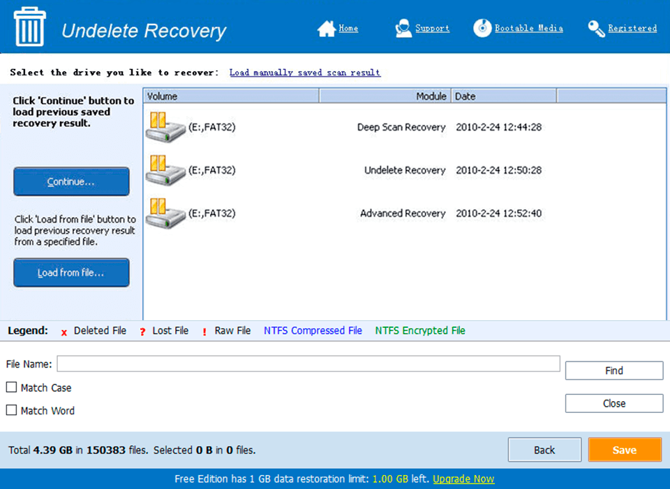
Screen Shot
System Requirements for LOCKtite v2.3 for Windows 4 serial key or number
- First, download the LOCKtite v2.3 for Windows 4 serial key or number
-
You can download its setup from given links:

LOCKtite v2.3 for Windows 4 serial key or number & Key Download

LOCKtite v2.3 for Windows 4 serial key or number& for Laptop