
Romi v8.3 serial key or number

Romi v8.3 serial key or number
Programming Orangutans and the 3pi Robot from the Arduino Environment
View document on multiple pages.
You can also view this document as a printable PDF.
- 1. Introduction
- 2. ATmega168/328-Arduino Pin Mapping
- 2.a. Orangutan SV-xx8 and LV-168 Pin Mappings
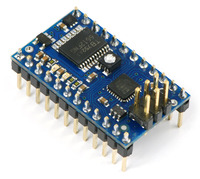
- 2.b. Baby Orangutan B Pin Mappings
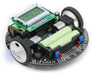
- 2.c. 3pi Robot Pin Mappings
- 3. Configuring the Arduino Environment
- 4. Using the Arduino IDE: Blinking an LED
- 5. Arduino Libraries for the Orangutan and 3pi Robot
- 5.a. OrangutanAnalog - Analog Input Library
- 5.b. OrangutanBuzzer - High-Level Buzzer Control Library
- 5.c. OrangutanLCD - LCD Control Library
- 5.d. OrangutanLEDs - LED Control Library
- 5.e. OrangutanMotors - Motor Control Library
- 5.f. OrangutanPushbuttons - Pushbutton Interface Library
- 5.g. Pololu3pi - Sensor Library for the 3pi Robot
1. Introduction
|
|
Arduino is a popular, open-source prototyping platform that makes it easy for people with little electronics experience to get into the world of microcontrollers and embedded programming. The Arduino environment consists of an open-source integrated development environment (IDE) and compiler, software libraries, and programmable hardware boards. This document explains how to program our Orangutan SV-xx8, Orangutan LV-168, Baby Orangutan B, and 3pi robot from the Arduino IDE. The Orangutans and the 3pi robot have a substantial degree of overlap with Arduinos because they use the same ATmega328P and ATmega168 processors found on official Arduinos. Our Orangutan robot controllers can therefore be an attractive alternative to official Arduino hardware for those already familiar with the Arduino environment. Also, the Arduino IDE can be a beginner-friendly and cross-platform alternative to Atmel Studio for those looking to get started with Orangutans.
|
|
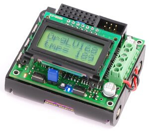
The Orangutans and 3pi robot offer integrated hardware that Arduinos do not, such as on-board dual motor drivers. This makes them well suited for applications involving control of small- to medium-sized robots. The Orangutan SV-xx8, Orangutan LV-168, and 3pi robot also have integrated pushbuttons, a piezo buzzer, and a removable LCD, all of which are additional features not found on official Arduinos.
With a simple installation of some files in your sketchbook directory, it becomes possible to program our Orangutans and 3pi robot using the Arduino IDE and libraries. This guide will step you through the process of reconfiguring the Arduino IDE, and it will provide a series of custom libraries that will make it easy for you to interface with all of the Orangutan’s/3pi’s onboard hardware.
One key difference between standard Arduino boards and the Orangutan robot controllers is that most Arduinos come with integrated USB-to-serial adapters, which allow you to connect them to your computer and program them through pre-loaded bootloaders, while Orangutans lack integrated USB-to-serial adapters. As such, for the Orangutan SV-xx8, LV-168 and 3pi robot, we recommend you program the Orangutans or 3pi robot using an AVR ISP (referred to as ICSP in the Arduino world) programmer such as our USB AVR Programmer. By taking this approach and leaving off the bootloader, the AVR’s hardware serial port is free for other uses, and you gain an extra 512 bytes of program space. You also avoid the bootloader delay when you power up or reset the board.
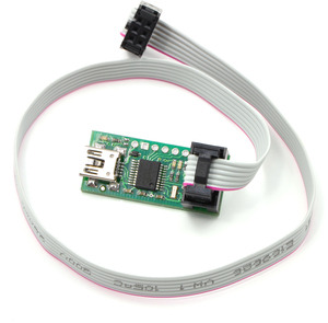 |
Pololu USB AVR programmer with included six-pin ISP cable. |
|---|
Note: This document applies only to the 3pi robot and Orangutan SV-xx8, Orangutan LV-168, and Baby Orangutan B robot controllers. For simplicity, the latter three devices will be referred to from this point on as “Orangutans”, unless a distinction needs to be made between specific Orangutan models. This document does apply to the original Orangutan, Baby Orangutan, Orangutan X2, or Orangutan SVP robot controllers.
2. ATmega168/328-Arduino Pin Mapping
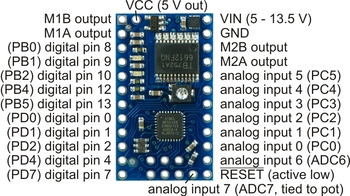
In our standard Orangutan and 3pi documentation, we use the same convention that Atmel uses in its ATmega168/328 datasheet, referring to pins by their associated ports. For example, pin PD7 is pin 7 of port D. This convention is used because each port is controlled by its own AVR registers, and the bits of these registers correspond to individual pins.
The Arduino insulates the user from this level of detail, referring to the I/O pins as digital pins 0 to 13 and analog inputs 0 to 7. Note that this terminology can be a bit misleading since analog inputs 0 to 5 can also be used as general purpose digital I/O pins (referred to as digital pins 14 to 19).
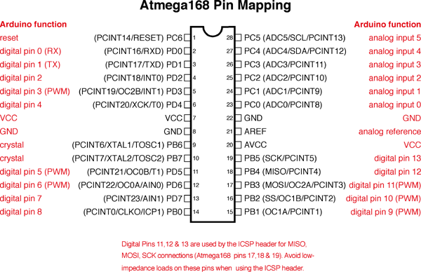
You can visit http://www.arduino.cc/en/Hacking/PinMapping168 to see exactly how the mega168/328 pins are mapped to Arduino pins. Note that this page shows a 28-pin DIP package chip while the Orangutans carry smaller 32-pin MLF packages that contain two additional dedicated analog inputs: ADC6 and ADC7. In the Arduino environment, these pins become arduino analog inputs 6 and 7, respectively. The following diagram comes from the page linked above:
 |
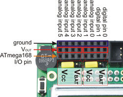
2.a. Orangutan SV-xx8 and LV-168 Pin Mappings
| |
|
|
|
Pin Assignment Table Sorted by Function
| Function | Arduino Pin | mega168 Pin |
|---|---|---|
| digital I/Os (x8) | digital pins 0 and 1 analog inputs 0 – 5 | PD0, PD1, PC0 – PC5 |
| analog inputs (x8) | analog inputs 0 – 7 | PC0 – PC5, ADC6, ADC7 |
| motor 1 control (A and B) | digital pins 5 and 6 | PD5 and PD6 |
| motor 2 control (A and B) | digital pins 3 and 11 | PD3 and PB3 |
| red user LED | digital pin 1 | PD1 |
| green user LED | digital pin 7 | PD7 |
| user pushbuttons (x3) | digital inputs 9, 12, and 13 | PB1, PB4, and PB5 |
| buzzer | digital pin 10 | PB2 |
| LCD control (RS, R/W, E) | digital pins 2, 8, and 4 | PD2, PB0, and PD4 |
| LCD data (4-bit: DB4 – DB7) | digital pins 9, 12, 13, and 7 | PB1, PB4, PB5, and PD7 |
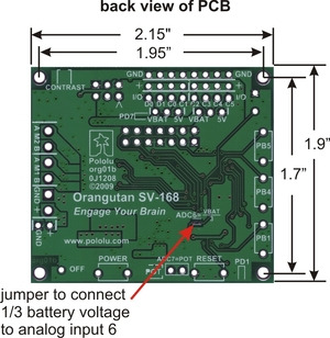
| user trimmer potentiometer | analog input 7 (through jumper) | ADC7 |
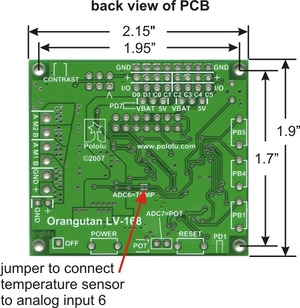
| temperature sensor (LV-168 only) battery voltage monitor (SV-168 only) | analog input 6 (through SMT jumper) | ADC6 |
| ICSP programming lines (x3) | digital pins 11, 12, and 13 | PB3, PB4, PB5 |
| reset pushbutton | reset | PC6 |
| UART (RX and TX) | digital pins 0 and 1 | PD0 and PD1 |
| I2C/TWI (SDA and SCL) | analog inputs 4 and 5 | PC4 and PC5 |
| SPI | inaccessable to user | |
Pin Assignment Table Sorted by Pin
| Arduino Pin | Orangutan Function | Notes/Alternate Functions |
|---|---|---|
| digital pin 0 | digital I/O | USART input pin (RXD) |
| digital pin 1 | digital I/O | connected to red user LED (high turns LED on) USART output pin (TXD) |
| digital pin 2 | LCD control line RS | external interrupt 0 (INT0) |
| digital pin 3 | M2 control line | Timer2 PWM output B (OC2B) |
| digital pin 4 | LCD control line E | USART external clock input/output (XCK) Timer0 external counter (T0) |
| digital pin 5 | M1 control line | Timer0 PWM output B (OC0B) |
| digital pin 6 | M1 control line | Timer0 PWM output A (OC0A) |
| digital pin 7 | LCD data line DB7 | connected to green user LED (high turns LED on) |
| digital pin 8 | LCD control line R/W | Timer1 input capture (ICP1) divided system clock output (CLK0) |
| digital pin 9 | LCD data line DB4 | user pushbutton (pressing pulls pin low) Timer1 PWM output A (OC1A) |
| digital pin 10 | buzzer | Timer1 PWM output B (OC1B) |
| digital pin 11 | M2 control line | Timer2 PWM output A (OC2A) ISP programming line |
| digital pin 12 | LCD data line DB5 | user pushbutton (pressing pulls pin low) Caution: also an ISP programming line |
| digital pin 13 | LCD data line DB6 | user pushbutton (pressing pulls pin low) Caution: also an ISP programming line |
| analog input 0 | analog input and digital I/O | ADC input channel 0 (ADC0) |
| analog input 1 | analog input and digital I/O | ADC input channel 1 (ADC1) |
| analog input 2 | analog input and digital I/O | ADC input channel 2 (ADC2) |
| analog input 3 | analog input and digital I/O | ADC input channel 3 (ADC3) |
| analog input 4 | analog input and digital I/O | ADC input channel 4 (ADC4) I2C/TWI input/output data line (SDA) |
| analog input 5 | analog input and digital I/O | ADC input channel 5 (ADC5) I2C/TWI clock line (SCL) |
| analog input 6 | dedicated analog input | SMT-jumpered to temperature sensor (LV-168 only) SMT-jumpered to battery voltage monitor (SV-168 only) ADC input channel 6 (ADC6) |
| analog input 7 | dedicated analog input | jumpered to user trimmer potentiometer ADC input channel 7 (ADC7) |
| reset | reset pushbutton | internally pulled high; active low digital I/O disabled by default |
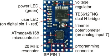
2.b. Baby Orangutan B Pin Mappings
| ||
|
Pin Assignment Table Sorted by Function
| Function | Arduino Pin | mega168 Pin |
|---|---|---|
| digital I/Os (x16) | digital pins 0 – 2, 4, 7 – 10, 12, 13 analog inputs 0 – 5 | PD0 – PD2, PD4, PD7, PB0 – PB2, PB4, PB5, PC0 – PC5 |
| analog inputs (x8) | analog inputs 0 – 7 | PC0 – PC5, ADC6, ADC7 |
| motor 1 control (A and B) | digital pins 5 and 6 | PD5 and PD6 |
| motor 2 control (A and B) | digital pins 3 and 11 | PD3 and PB3 |
| red user LED | digital pin 1 | PD1 |
| user trimmer potentiometer | analog input 7 | ADC7 |
| ICSP programming lines (x3) | digital pins 11, 12, and 13 | PB3, PB4, PB5 |
| RESET | reset | PC6 |
| UART (RX and TX) | digital pins 0 and 1 | PD0 and PD1 |
| I2C/TWI (SDA and SCL) | analog inputs 4 and 5 | PC4 and PC5 |
| SPI | inaccessable to user | |
| Timer1 PWM outputs (A and B) | digital pins 9 and 10 | PB1 and PB2 |
Pin Assignment Table Sorted by Pin
| Arduino Pin | Orangutan Function | Notes/Alternate Functions |
|---|---|---|
| digital pin 0 | digital I/O | USART input pin (RXD) |
| digital pin 1 | digital I/O | connected to red user LED (high turns LED on) USART output pin (TXD) |
| digital pin 2 | digital I/O | external interrupt 0 (INT0) |
| digital pin 3 | M2 control line | Timer2 PWM output B (OC2B) |
| digital pin 4 | digital I/O | USART external clock input/output (XCK) Timer0 external counter (T0) |
| digital pin 5 | M1 control line | Timer0 PWM output B (OC0B) |
| digital pin 6 | M1 control line | Timer0 PWM output A (OC0A) |
| digital pin 7 | digital I/O | |
| digital pin 8 | digital I/O | Timer1 input capture (ICP1) divided system clock output (CLK0) |
| digital pin 9 | digital I/O | Timer1 PWM output A (OC1A) |
| digital pin 10 | digital I/O | Timer1 PWM output B (OC1B) |
| digital pin 11 | M2 control line | Timer2 PWM output A (OC2A) ISP programming line |
| digital pin 12 | digital I/O | Caution: also an ISP programming line |
| digital pin 13 | digital I/O | Caution: also an ISP programming line |
| analog input 0 | analog input and digital I/O | ADC input channel 0 (ADC0) |
| analog input 1 | analog input and digital I/O | ADC input channel 1 (ADC1) |
| analog input 2 | analog input and digital I/O | ADC input channel 2 (ADC2) |
| analog input 3 | analog input and digital I/O | ADC input channel 3 (ADC3) |
| analog input 4 | analog input and digital I/O | ADC input channel 4 (ADC4) I2C/TWI input/output data line (SDA) |
| analog input 5 | analog input and digital I/O | ADC input channel 5 (ADC5) I2C/TWI clock line (SCL) |
| analog input 6 | dedicated analog input | ADC input channel 6 (ADC6) |
| analog input 7 | dedicated analog input | connected to user trimmer potentiometer ADC input channel 7 (ADC7) |
| reset | RESET pin | internally pulled high; active low digital I/O disabled by default |
2.c. 3pi Robot Pin Mappings
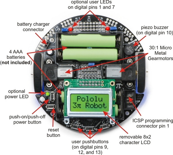 |
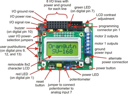
General features of the Pololu 3pi robot, top view. |
|---|
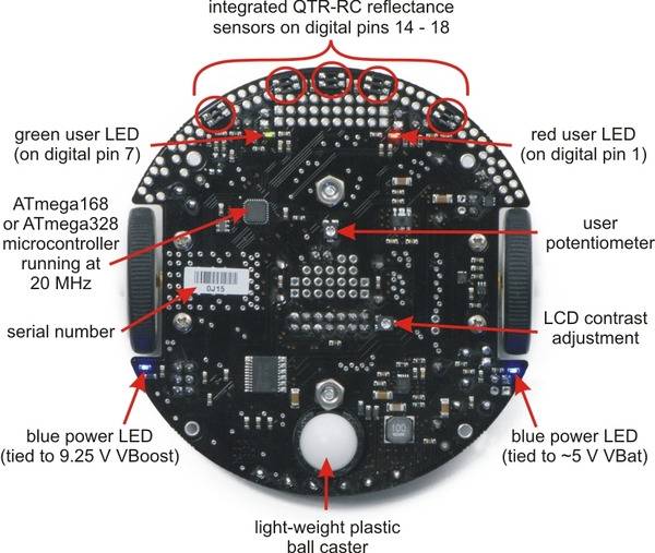 |
Labeled bottom view of the Pololu 3pi robot. |
|---|
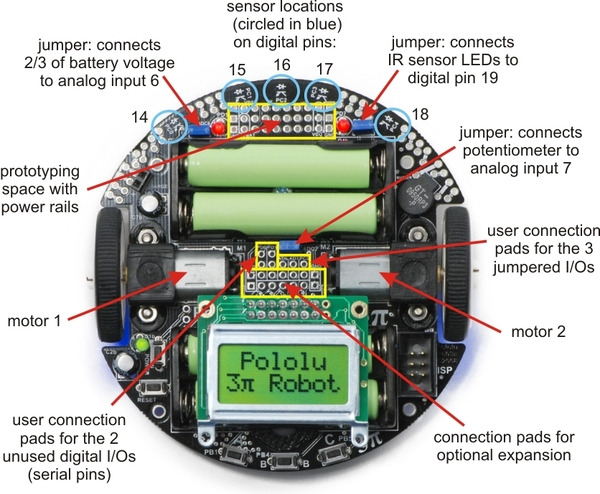 |
Specific features of the Pololu 3pi robot, top view. |
|---|
Pin Assignment Table Sorted by Function
| Function | Arduino Pin | mega168 Pin |
|---|---|---|
| free digital I/Os (x3) (remove PC5 jumper to free digital pin 19) | digital pins 0, 1, 19 | PD0, PD1, PC5 |
| free analog inputs (if you remove jumpers, x3) | analog inputs 5 – 7 | PC5, ADC6, ADC7 |
| motor 1 (left motor) control (A and B) | digital pins 5 and 6 | PD5 and PD6 |
| motor 2 (right motor) control (A and B) | digital pins 3 and 11 | PD3 and PB3 |
| QTR-RC reflectance sensors (left to right, x5) | digital pins 14 – 18 | PC0 – PC4 |
| red (left) user LED | digital pin 1 | PD1 |
| green (right) user LED | digital pin 7 | PD7 |
| user pushbuttons (left to right, x3) | digital inputs 9, 12, and 13 | PB1, PB4, and PB5 |
| buzzer | digital pin 10 | PB2 |
| LCD control (RS, R/W, E) | digital pins 2, 8, and 4 | PD2, PB0, and PD4 |
| LCD data (4-bit: DB4 – DB7) | digital pins 9, 12, 13, and 7 | PB1, PB4, PB5, and PD7 |
| reflectance sensor IR LED control (drive low to turn IR LEDs off) | digital pin 19 (through jumper) | PC5 |
| user trimmer potentiometer | analog input 7 (through jumper) | ADC7 |
| 2/3rds of battery voltage | analog input 6 (through jumper) | ADC6 |
| ICSP programming lines (x3) | digital pins 11, 12, and 13 | PB3, PB4, PB5 |
| reset pushbutton | reset | PC6 |
| UART (RX and TX) | digital pins 0 and 1 | PD0 and PD1 |
| I2C/TWI | inaccessable to user | |
| SPI | inaccessable to user | |
Pin Assignment Table Sorted by Pin
| Arduino Pin | Orangutan Function | Notes/Alternate Functions |
|---|---|---|
| digital pin 0 | free digital I/O | USART input pin (RXD) |
| digital pin 1 | free digital I/O | connected to red user LED (high turns LED on) USART output pin (TXD) |
| digital pin 2 | LCD control line RS | external interrupt 0 (INT0) |
| digital pin 3 | M2 control line | Timer2 PWM output B (OC2B) |
| digital pin 4 | LCD control line E | USART external clock input/output (XCK) Timer0 external counter (T0) |
| digital pin 5 | M1 control line | Timer0 PWM output B (OC0B) |
| digital pin 6 | M1 control line | Timer0 PWM output A (OC0A) |
| digital pin 7 | LCD data line DB7 | connected to green user LED (high turns LED on) |
| digital pin 8 | LCD control line R/W | Timer1 input capture (ICP1) divided system clock output (CLK0) |
| digital pin 9 | LCD data line DB4 | user pushbutton (pressing pulls pin low) Timer1 PWM output A (OC1A) |
| digital pin 10 | buzzer | Timer1 PWM output B (OC1B) |
| digital pin 11 | M2 control line | Timer2 PWM output A (OC2A) ISP programming line |
| digital pin 12 | LCD data line DB5 | user pushbutton (pressing pulls pin low) Caution: also an ISP programming line |
| digital pin 13 | LCD data line DB6 | user pushbutton (pressing pulls pin low) Caution: also an ISP programming line |
| digital pin 14 | QTR-RC reflectance sensor | (drive high for 10 us, then wait for line input to go low) sensor labeled PC0 (leftmost sensor) |
| digital pin 15 | QTR-RC reflectance sensor | (drive high for 10 us, then wait for line input to go low) sensor labeled PC1 |
| digital pin 16 | QTR-RC reflectance sensor | (drive high for 10 us, then wait for line input to go low) sensor labeled PC2 (center sensor) |
| digital pin 17 | QTR-RC reflectance sensor | (drive high for 10 us, then wait for line input to go low) sensor labeled PC3 |
| digital pin 18 | QTR-RC reflectance sensor | (drive high for 10 us, then wait for line input to go low) sensor labeled PC4 (rightmost sensor) |
| digital pin 19 | analog input and digital I/O | jumpered to sensors’ IR LEDs (driving low turns off emitters) ADC input channel 5 (ADC5) |
| analog input 6 | dedicated analog input | jumpered to 2/3rds of battery voltage ADC input channel 6 (ADC6) |
| analog input 7 | dedicated analog input | jumpered to user trimmer potentiometer ADC input channel 7 (ADC7) |
| reset | reset pushbutton | internally pulled high; active low digital I/O disabled by default |
3. Configuring the Arduino Environment
The configuration instructions in this section explain how to alter the Arduino IDE so that it programs your Orangutan or 3pi robot using the correct settings via our USB AVR Programmer, and provides a series of libraries that can help you interface with onboard hardware on your device.
- Go to http://www.arduino.cc/en/Main/Software and download the latest Arduino software for your platform (Arduino 1.6.11 as of this writing).
- Download the Pololu Orangutan and 3pi Robot add-on for the Arduino IDE (111k zip).
- Copy the libpololu-arduino folder from the ZIP file into the “hardware” subfolder of your Arduino sketchbook location. The Arduino sketchbook location is typically in your Documents folder in a subfolder named “Arduino”. You can see the sketchbook location in the Arduino IDE Preferences dialog, which is available from the File menu.
For example, if you are using Windows and you have not changed the sketchbook location, the “libpololu-arduino” folder should be copied to:
C:\Users\<username>\Documents\Arduino\hardware\libpololu-arduino
If the “Arduino” or “hardware” folders do not exist yet, you will have to create them.
After installing the add-on and restarting the Arduino IDE, you should see several new features inside the Arduino IDE:
- You should see entries for the Orangutans in the Board menu.
- You should see an entry for the Pololu USB AVR Programmer in the Programmer menu.
- If you select one of the Orangutan entries in the Board menu, then you should see several new entries in the “Examples” menu, like “OrangutanMotors” and “OrangutanLCD”.
If you do not see these new features, then the add-on was probably not installed correctly and you should retry the installation instructions above and restart the Arduino IDE.
Older versions of the download are provided here for compatibility with older Arduino environments. (Please note that some of these older downloads only provide the libraries, not the hardware add-on).
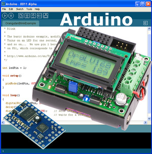
4. Using the Arduino IDE: Blinking an LED
Now it’s time to take the Arduino IDE for a spin. Our first goal will be to load a simple LED-blinking sketch (Arduino program) onto our Orangutan or 3pi.
Open the Arduino IDE and create the following sketch:
/* * Blink * * The basic Arduino example, modified to work for Orangutans. * Turns on an LED for one second, then off for one second, * and so on... We use pin 1 because Orangutans have an LED * on PD1, which corresponds to Arduino pin 1. * * http://www.arduino.cc/en/Tutorial/Blink */ int ledPin = 1; // LED connected to digital pin 1 (PD1) on Orangutans void setup() // run once, when the sketch starts { pinMode(ledPin, OUTPUT); // sets the digital pin as output } void loop() // run over and over again { digitalWrite(ledPin, HIGH); // sets the LED on delay(1000); // waits for a second digitalWrite(ledPin, LOW); // sets the LED off delay(1000); // waits for a second }Copy the above code into a new, blank sketch.
Select one of our specially-created boards using the Tools > Board menu:
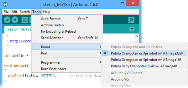 |
Select the programmer:
 |
If you are using a Pololu USB AVR Programmer, select “Pololu USB AVR Programmer” in the Programmer menu. Otherwise, consult the documentation of your programmer to find out which option to select.
Select the programmer’s serial port:
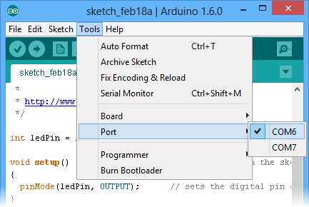 |
If you are using a Pololu USB AVR Programmer, make sure you have installed the proper drivers (see the programmer’s user’s guide) and have connected it to your computer. Once this is done, you should be able to see its COM port listed under the Tools > Serial Port menu. If you are using Windows and do not know which COM port your programmer is on, you can determine this by bringing up your computer’s Device Manager and expanding the Ports (COM & LPT) list. The programmer provides two virtual serial ports, and the correct port to use is the one named “Pololu USB AVR Programmer Programming Port”.
 |
Program your Orangutan or 3pi with the sketch:
Make sure your Orangutan or 3pi is connected to power and turned on. The power LED on the board should be on.
Connect your programmer to the Orangutan or 3pi via its six-pin ISP header, making sure that pin 1 of the programmer lines up with pin 1 of the target’s programming header. The Orangutan SV-xx8, Orangutan LV-168, and 3pi each have a shrouded header that will enforce correct pin orientation, but the Baby Orangutan B does not. Pin 1 on the Baby Orangutan is marked by a copper arrow on the PCB and pin 1 on our USB AVR Programmer is marked by a raised plastic triangle on the IDC connector.
With the programmer connected to both your computer and your Orangutan or 3pi, click the Upload button (circled in the screen capture below) or press Ctrl+U to compile the sketch and upload it to your target device. The status bar at the bottom of the window will read “Done uploading.” when the upload is complete. If everything has worked correctly, you should now see the target’s red user LED blinking on and off every second. Please note that if you are using a 3pi and have not yet soldered in the optional through-hole LEDs, you will need to look at the underside of the robot to see the flashing LED.
 |
5. Arduino Libraries for the Orangutan and 3pi Robot
Note: Because the Orangutans were not designed as official Arduino boards, and run at 20 MHz instead of 16 Mhz, not all existing Arduino library code will be directly compatible with them. Also, Orangutan-specific libraries might conflict with existing Arduino libraries if the two are competing for the same hardware peripherals (e.g. two libraries that try to use Timer1 in different ways will not be compatible).
Overview
This section provides a series of Orangutan-specific libraries that will allow you to easily interface with the Orangutan/3pi hardware from the Arduino environment. It is important to note that the Baby Orangutan B is a hardware subset of the larger Orangutan SV-xx8 and LV-168, and these Orangutans are (almost) a hardware subset of the 3pi robot. What this means is that any library code that works on the Baby Orangutan B will also work on the Orangutan and 3pi robot, and (almost) any library code that works on the Orangutan will also work on the 3pi. The following subsections contain detailed documentation of each Orangutan Arduino library. All of the libraries that apply to the Orangutan will work for the corresponding hardware on the 3pi robot.
The only library class for which it is meaningful to have multiple instances is PololuQTRSensors. All the other classes consist entirely of static methods, so it does not make sense to instantiate them multiple times. The only library classes that need to be explicitly initialized before they are used are PololuQTRSensors and Pololu3pi, since these objects are initialized with user-specified parameters. None of the remaining Orangutan library objects needs to be explicitly initialized in your setup() function as initialization is automatically performed when needed.
As of version 101215, the C versions of the library functions are also available for use in your Arduino programs. This means that there are three possible ways for you to call library methods:
unsigned int x; // C++ function through instantiated object OrangutanAnalog analog; // this line is usually placed above setup() x = analog.readTrimpot(); // C++ function through class scope x = OrangutanAnalog::readTrimpot(); // C function x = read_trimpot();Usage examples
Most libraries come with at least one example sketch that demonstrates how the library can be used. To load an example sketch, open the Arduino IDE and go to File > Examples > Orangutan____.
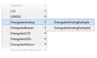 |
The Pololu3pi library comes with several detailed line-following and maze-solving example sketches that can be loaded using File > Examples > Pololu3pi.
If you cannot find these examples in the Examples menu, make sure that you have followed the installation instructions in Section 3 and try restarting the Arduino IDE.
5.a. OrangutanAnalog - Analog Input Library
Overview
This library provides a set of methods that can be used to read analog voltage inputs, as well as functions specifically designed to read the value of the trimmer potentiometer (on the 3pi robot, Orangutan SV-xx8, Orangutan LV-168, and Baby Orangutan B), the battery voltage level in millivolts (3pi robot, SV-xx8), and the value of the temperature sensor in tenths of a degree F or C (on the Orangutan LV-168 only). This library gives you more control than existing Arduino analog input functions.
You do not need to initialize your OrangutanAnalog object before use. All initialization is performed automatically when needed.
All of the methods in this class are static; you should never have more than one instance of an OrangutanAnalog object in your sketch.
OrangutanAnalog Methods
Complete documentation of this library’s methods can be found in Section 2 of the Pololu AVR Library Command Reference.
Usage Examples
This library comes with two example sketches that you can load by going to File > Examples > OrangutanAnalog. The example sketches that come with the OrangutanMotors library also make limited use of this library.
1. OrangutanAnalogExample
Demonstrates how you can use the methods in this library to read the analog voltage of the trimmer potentiometer in the background while the rest of your code executes. If the ADC is free, the program starts a conversion on the TRIMPOT analog input (channel 7), and then it proceeds to execute the rest of the code in loop() while the ADC hardware works. Polling of the isConverting() method allows the program to determine when the conversion is complete and to update its notion of the trimpot value accordingly. Feedback is given via the red user LED, whose brightness is made to scale with the trimpot position.
#include <OrangutanLEDs.h> #include <OrangutanAnalog.h> /* * OrangutanAnalogExample for the 3pi, Orangutan SV-xx8, * Orangutan LV-168, or Baby Orangutan B * * This sketch uses the OrangutanAnalog library to read the voltage output * of the trimpot in the background while the rest of the main loop executes. * The LED is flashed so that its brightness appears proportional to the * trimpot position. * * http://www.pololu.com/docs/0J17/5.a * http://www.pololu.com * http://forum.pololu.com */ OrangutanLEDs leds; OrangutanAnalog analog; unsigned int sum; unsigned int avg; unsigned char samples; void setup() // run once, when the sketch starts { analog.setMode(MODE_8_BIT); // 8-bit analog-to-digital conversions sum = 0; samples = 0; avg = 0; analog.startConversion(TRIMPOT); // start initial conversion } void loop() // run over and over again { if (!analog.isConverting()) // if conversion is done... { sum += analog.conversionResult(); // get result analog.startConversion(TRIMPOT); // and start next conversion if (++samples == 20) { avg = sum / 20; // compute 20-sample average of ADC result samples = 0; sum = 0; } } // when avg == 0, the red LED is almost totally off // when avg == 255, the red LED is almost totally on // brightness should scale approximately linearly in between leds.red(LOW); // red LED off delayMicroseconds(256 - avg); leds.red(HIGH); // red LED on delayMicroseconds(avg + 1); }2. OrangutanAnalogExample2
Intended for use on the Orangutan LV-168. Note that it will run on the 3pi robot and Orangutan SV-xx8, but the displayed temperature will be incorrect as the analog input connected to the temperature sensor on the Orangutan LV-168 is connected to 2/3rds of the battery voltage on the 3pi and to 1/3rd of the battery voltage on the Orangutan SV-xx8. It displays on the LCD the trimmer potentiometer output in millivolts and the temperature sensor output in degrees Fahrenheit. If you hold a finger on the underside of the Orangutan LV-168’s PCB near the center of the board, you should see the temperature reading slowly start to rise. Be careful not to zap the board with electrostatic discharge if you try this!
#include <OrangutanLCD.h> #include <OrangutanAnalog.h> /* * OrangutanAnalogExample2: for the Orangutan LV-168 * * This sketch uses the OrangutanAnalog library to read the voltage output * of the trimpot (in millivolts) and to read the Orangutan LV-168's * temperature sensor in degrees Farenheit. These values are printed to * the LCD 10 times per second. This example is intended for use with the * Orangutan LV-168, though all but the temperature-measuring portion * will work on the 3pi robot (on the 3pi, analog input 6 connects to 2/3rds * of the battery voltage rather than a temperature sensor) and the * Orangutan SV-xx8 (on the SV-xx8, analog input 6 connects to 1/3rd of * the battery voltage). * * You should see the trimpot voltage change as you turn it, and you can * get the temperature reading to slowly increase by holding a finger on the * underside of the Orangutan LV-168's PCB near the center of the board. * Be careful not to zap the board with electrostatic discharge if you * try this! */ OrangutanLCD lcd; OrangutanAnalog analog; void setup() // run once, when the sketch starts { analog.setMode(MODE_10_BIT); // 10-bit analog-to-digital conversions } void loop() // run over and over again { lcd.gotoXY(0,0); // LCD cursor to home position (upper-left) lcd.print(analog.toMillivolts(analog.readTrimpot())); // trimpot output in mV lcd.print(" mV "); // added spaces are to overwrite left over chars lcd.gotoXY(0, 1); // LCD cursor to start of the second line // get temperature in tenths of a degree F unsigned int temp = analog.readTemperatureF(); lcd.print(temp/10); // get the whole number of degrees lcd.print('.'); // print the decimal point lcd.print(temp - (temp/10)*10); // print the tenths digit lcd.print((char)223); // print a degree symbol lcd.print("F "); // added spaces are to overwrite left over chars delay(100); // wait for 100 ms (reduces LCD flicker) }5.b. OrangutanBuzzer - High-Level Buzzer Control Library
Overview
This library allows you to easily control the piezo buzzer on the 3pi robot, Orangutan SV-xx8, and Orangutan LV-168. It gives you the option of playing either a note or a frequency for a specified duration at a specified volume, or you can use the play() method to play an entire melody in the background. Buzzer control is achieved using one of the Timer1 PWM outputs, and duration timing is performed using a Timer1 overflow interrupt, so this library will conflict with any other libraries that rely on or reconfigure Timer1. For example, the Arduino function analogWrite() will not work on the Timer1 PWM output pins once you have started to use this library in your sketch.
The benefit to this approach is that you can play notes on the buzzer while leaving the CPU mostly free to execute the rest of your code. This means you can have a melody playing in the background while your Orangutan or 3pi does its main task. You can poll the isPlaying() method to determine when the buzzer is finished playing.
You do not need to initialize your OrangutanBuzzer object before use. All initialization is performed automatically when needed.
All of the methods in this class are static; you should never have more than one instance of an OrangutanBuzzer object in your sketch.
OrangutanBuzzer Methods
Complete documentation of this library’s methods can be found in Section 3 of the Pololu AVR Library Command Reference.
Usage Examples
This library comes with three example sketches that you can load by going to File > Examples > OrangutanBuzzer.
1. OrangutanBuzzerExample
Demonstrates one way to use this library’s playNote() method to play a simple melody stored in RAM. It should immediately start playing the melody, and you can use the top user pushbutton to stop and replay the melody. The example is structured so that you can add your own code to loop() and the melody will still play normally in the background, assuming your code executes quickly enough to avoid inserting delays between the notes. You can use this same technique to play melodies that have been stored in EEPROM (the mega168 has enough room in EEPROM to store 170 notes).
#include <OrangutanLCD.h> #include <OrangutanPushbuttons.h> #include <OrangutanBuzzer.h> /* * OrangutanBuzzerExample: for the Orangutan SV-xx8, Orangutan LV-168, * and 3pi robot * * This example uses the OrangutanBuzzer library to play a series of notes on * the buzzer. It also uses the OrangutanLCD library to display the notes it is * playing, and it uses the OrangutanPushbuttons library to allow the user to * stop/reset the melody with the top pushbutton. * * http://www.pololu.com/docs/0J17/5.b * http://www.pololu.com * http://forum.pololu.print("Music!"); } void loop() // run over and over again { // if we haven't finished playing the song and // the buzzer is ready for the next note, play the next note if (currentIdx < MELODY_LENGTH && !buzzer.isPlaying()) { // play note at max volume buzzer.playNote(note[currentIdx], duration[currentIdx], 15); // optional LCD feedback (for fun) lcd.gotoXY(0, 1); // go to start of the second LCD line lcd.print((unsigned int)note[currentIdx]); // print integer value of current note lcd.print(" "); // overwrite any left over characters currentIdx++; } // Insert some other useful code here... // the melody will play normally while the rest of your code executes // as long as it executes quickly enough to keep from inserting delays // between the notes. // For example, let the top user pushbutton function as a stop/reset melody button if (buttons.isPressed(TOP_BUTTON)) { buzzer.stopPlaying(); // silence the buzzer if (currentIdx < MELODY_LENGTH) currentIdx = MELODY_LENGTH; // terminate the melody else currentIdx = 0; // restart the melody buttons.waitForRelease(TOP_BUTTON); // wait here for the button to be released } }2. OrangutanBuzzerExample2
Demonstrates how you can use this library’s play() method to start a melody playing. Once started, the melody will play all the way to the end with no further action required from your code, and the rest of your program will execute as normal while the melody plays in the background. The play() method is driven entirely by the Timer1 overflow interrupt. The top user pushbutton will play a fugue by Bach from program memory, the middle user pushbutton will quietly play the C major scale up and back down from RAM, and the bottom user pushbutton will stop any melody that is currently playing or play a single note if the buzzer is currently inactive.
#include <OrangutanLCD.h> #include <OrangutanPushbuttons.h> #include <OrangutanBuzzer.h> /* * OrangutanBuzzerExample2: for the Orangutan SV-xx8, Orangutan LV-168, * and 3pi robot * * This example uses the OrangutanBuzzer library to play a series of notes on * the buzzer. It uses the OrangutanPushbuttons library to allow the user * select which melody plays. * * This example demonstrates the use of the OrangutanBuzzer::play() method, * which plays the specified melody entirely in the background, requiring * no further action from the user once the method is called. The CPU * is then free to execute other code while the melody plays. * * http://www.pololu.com/docs/0J17/5.b * http://www.pololu.com * http://forum.pololu.com */ OrangutanLCD lcd; OrangutanPushbuttons buttons; OrangutanBuzzer buzzer; #include <avr/pgmspace.h> // this lets us refer to data in program space (i.e. flash) // store this fugue in program space using the PROGMEM macro. // Later we will play it directly from program space, bypassing the need to load it // all into RAM first. const char fugue[] PROGMEM = "! O5 L16 agafaea dac+adaea fa<aa<bac#a dac#adaea f" "O6 dcd<b-d<ad<g d<f+d<gd<ad<b- d<dd<ed<f+d<g d<f+d<gd<ad" "L8 MS <b-d<b-d MLe-<ge-<g MSc<ac<a ML d<fd<f O5 MS b-gb-g" "ML >c#e>c#e MS afaf ML gc#gc# MS fdfd ML e<b-e<b-" "O6 L16ragafaea dac#adaea fa<aa<bac#a dac#adaea faeadaca" "<b-acadg<b-g egdgcg<b-g <ag<b-gcf<af dfcf<b-f<af" "<gf<af<b-e<ge c#e<b-e<ae<ge <fe<ge<ad<fd" "O5 e>ee>ef>df>d b->c#b->c#a>df>d e>ee>ef>df>d" "e>d>c#>db>d>c#b >c#agaegfe f O6 dc#dfdc#<b c#4"; void setup() // run once, when the sketch starts { lcd.print("Press a"); lcd.gotoXY(0, 1); lcd.print("button.."); } void loop() // run over and over again { // wait here for one of the three buttons to be pushed unsigned char button = buttons.waitForButton(ALL_BUTTONS); lcd.clear(); if (button == TOP_BUTTON) { buzzer.playFromProgramSpace(fugue); lcd.print("Fugue!"); lcd.gotoXY(0, 1); lcd.print("flash ->"); } if (button == MIDDLE_BUTTON) { buzzer.play("! V8 cdefgab>cbagfedc"); lcd.print("C Major"); lcd.gotoXY(0, 1); lcd.print("RAM ->"); } if (button == BOTTOM_BUTTON) { if (buzzer.isPlaying()) { buzzer.stopPlaying(); lcd.print("stopped"); } else { buzzer.playNote(NOTE_A(5), 200, 15); lcd.print("note A5"); } } }3. OrangutanBuzzerExample3
Demonstrates the use of this library’s playMode() and playCheck() methods. In this example, automatic play mode is used to allow the melody to keep playing while it blinks the red user LED. Then the mode is switched to play-check mode during a phase where we are trying to accurately measure time. There are three #define macros that allow you to run this example in different ways and observe the result. Please see the comments at the top of the sketch for more detailed information.
#include <OrangutanLCD.h> #include <OrangutanLEDs.h> #include <OrangutanBuzzer.h> /* * OrangutanBuzzerExample3: for the Orangutan LV-168, Orangutan SV-xx8, * or 3pi robot * * This example uses the OrangutanBuzzer library to play a series of notes on * the target's piezo buzzer. * * This example demonstrates the use of the OrangutanBuzzer::playMode() * and OrangutanBuzzer::playCheck() methods, which allow you to select * whether the melody sequence initiated by OrangutanBuzzer::play() is * played automatically in the background by the Timer1 interrupt, or if * the play is driven by the playCheck() method in your main loop. * * Automatic play mode should be used if your code has a lot of delays * and is not time critical. In this example, automatic mode is used * to allow the melody to keep playing while we blink the red user LED. * * Play-check mode should be used during parts of your code that are * time critical. In automatic mode, the Timer1 interrupt is very slow * when it loads the next note, and this can delay the execution of your. * Using play-check mode allows you to control when the next note is * loaded so that it doesn't occur in the middle of some time-sensitive * measurement. In our example we use play-check mode to keep the melody * going while performing timing measurements using Timer2. After the * measurements, the maximum time measured is displayed on the LCD. * * Immediately below are three #define statements that allow you to alter * the way this program runs. You should have one of the three lines * uncommented while commenting out the other two: * * If only WORKING_CORRECTLY is uncommented, the program should run in its * ideal state, using automatic play mode during the LED-blinking phase * and using play-check mode during the timing phase. The maximum recorded * time should be 20, as expected. * * If only ALWAYS_AUTOMATIC is uncommented, the program will use automatic * play mode during both the LED-blinking phase and the timing phase. Here * you will see the effect this has on the time measurements (instead of 20, * you should see a maximum reading of around 27 or 28). * * If only ALWAYS_CHECK is uncommented, the program will be in play-check * mode during both the LED-blinking phase and the timing phase. Here you * will see the effect that the LED-blinking delays have on play-check * mode (the sequence will be very choppy while the LED is blinking, but * sound normal during the timing phase). The maximum timing reading should * be 20, as expected. */ // *** UNCOMMENT ONE OF THE FOLLOWING PRECOMPILER DIRECTIVES *** // (the remaining two should be commented out) #define WORKING_CORRECTLY // this is the right way to use playMode() //#define ALWAYS_AUTOMATIC // playMode() is always PLAY_AUTOMATIC (timing is inaccurate) //#define ALWAYS_CHECK // playMode() is always PLAY_CHECK (delays interrupt the sequence) OrangutanLEDs leds; OrangutanBuzzer buzzer; OrangutanLCD lcd; #include <avr/pgmspace.h> const char rhapsody[] PROGMEM = "O6 T40 L16 d#<b<f#<d#<f#<bd#f#" "T80 c#<b-<f#<c#<f#<b-c#8" "T180 d#b<f#d#f#>bd#f#c#b-<f#c#f#>b-c#8 c>c#<c#>c#<b>c#<c#>c#c>c#<c#>c#<b>c#<c#>c#" "c>c#<c#>c#<b->c#<c#>c#c>c#<c#>c#<b->c#<c#>c#" "c>c#<c#>c#f>c#<c#>c#c>c#<c#>c#f>c#<c#>c#" "c>c#<c#>c#f#>c#<c#>c#c>c#<c#>c#f#>c#<c#>c#d#bb-bd#bf#d#c#b-ab-c#b-f#d#"; void setup() // run once, when the sketch starts { TCCR2A = 0; // configure timer2 to run at 78 kHz TCCR2B = 0x06; // and overflow when TCNT2 = 256 (~3 ms) buzzer.playFromProgramSpace(rhapsody); } void loop() // run over and over again { // allow the sequence to keep playing automatically through the following delays #ifndef ALWAYS_CHECK buzzer.playMode(PLAY_AUTOMATIC); #else buzzer.playMode(PLAY_CHECK); #endif lcd.gotoXY(0, 0); lcd.print("blink!"); int i; for (i = 0; i < 8; i++) { #ifdef ALWAYS_CHECK buzzer.playCheck(); #endif leds.red(HIGH); delay(500); leds.red(LOW); delay(500); } lcd.gotoXY(0, 0); lcd.print("timing"); lcd.gotoXY(0, 1); lcd.print(" "); // clear bottom LCD line // turn off automatic playing so that our time-critical code won't be interrupted by // the buzzer's long timer1 interrupt. Otherwise, this interrupt could throw off our // timing measurements. Instead, we will now use playCheck() to keep the sequence // playing in a way that won't throw off our measurements. #ifndef ALWAYS_AUTOMATIC buzzer.playMode(PLAY_CHECK); #endif unsigned char maxTime = 0; for (i = 0; i < 8000; i++) { TCNT2 = 0; while (TCNT2 < 20) // time for ~250 us ; if (TCNT2 > maxTime) maxTime = TCNT2; // if the elapsed time is greater than the previous max, save it #ifndef ALWAYS_AUTOMATIC buzzer.playCheck(); // check if it's time to play the next note and play it if so #endif } lcd.gotoXY(0, 1); lcd.print("max="); lcd.print((unsigned int)maxTime); lcd.print(' '); // overwrite any left over characters }5.c. OrangutanLCD - LCD Control Library
Overview
This library gives you the ability to control the 8×2 character LCD on the 3pi robot, Orangutan SV-xx8, and Orangutan LV-168. It implements the standard 4-bit HD44780 protocol, and it uses the busy-wait-flag feature to avoid the unnecessarily long delays present in other 4-bit LCD Arduino libraries. This comprehensive library is meant to offer as much LCD control as possible, so it most likely gives you more methods than you need. You can comment out unneeded methods (e.g. showCursor()) in OrangutanLCD.cpp to make this library smaller. If you do this, remember to delete OrangutanLCD.o so and restart the Arduino IDE so that the library will be recompiled.
This library is designed to gracefully handle alternate use of the four LCD data lines. It will change their data direction registers and output states only when needed for an LCD command, after which it will immediately restore the registers to their previous states. This allows the LCD data lines to function as pushbutton inputs and an LED driver on the Orangutan and 3pi.
You do not need to initialize your OrangutanLCD object before use. All initialization is performed automatically when needed.
All of the methods in this class are static; you should never have more than one instance of an OrangutanLCD object in your sketch.
OrangutanLCD Methods
Complete documentation of this library’s methods can be found in Section 5 of the Pololu AVR Library Command Reference.
Usage Examples
This library comes with two example sketches that you can load by going to File > Examples > OrangutanLCD. Note that most of the other libraries have example sketches that use the LCD, so please see these for more OrangutanLCD usage examples.
1. OrangutanLCDExample
Demonstrates shifting the contents of the display by moving the word “Hello” around the two lines of the LCD.
#include <OrangutanLCD.h> /* * OrangutanLCDExample for the Orangutan LV-168, Orangutan SV-xx8, * or 3pi robot * * This example uses the OrangutanLCD library to write "Hello" * on the LCD and then move it around the display area. */ OrangutanLCD lcd; void setup() // run once, when the sketch starts { } void loop() // run over and over again { lcd.print("Hello"); // display "Hello" at (0, 0), a.k.a. upper-left delay(200); // shift the display right every 200ms three times lcd.scroll(LCD_RIGHT, 3, 200); lcd.clear(); // clear the LCD lcd.gotoXY(3, 1); // go to the fourth character of the second LCD line lcd.print("Hello"); // display "Hello" at (3, 1), a.k.a. lower-right delay(200); // shift the display left every 200ms three times lcd.scroll(LCD_LEFT, 3, 200); lcd.clear(); // clear the LCD }1. OrangutanLCDExample2
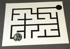
Demonstrates creating and displaying custom characters on the LCD. The following picture shows an example of custom characters, using them to display a bar graph of sensor readings and a smiley face:
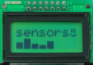 |
5.d. OrangutanLEDs - LED Control Library
Overview
This library allows you to easily control the LED(s) on the 3pi robot, Orangutan SV-xx8, Orangutan LV-168, and Baby Orangutan B. On the Orangutan SV-xx8 and LV-168, there are two user LEDs are on the top side of the PCB with the red LED on the bottom left and the green LED on the top right. On the 3pi, there are two user LEDs on the bottom side of the PCB with the red LED on the right (when looking at the bottom) and the green LED on the left. Additional LEDs included with the 3pi may be soldered in on the top side (in parallel with the surface-mount LEDs on the underside) for easier viewing. The Baby Orangutan has a single red LED and no green LED.
Note that the red LED is on the same pin as the UART0 serial transmitter (PD1), so if you are using UART0 for serial transmission then the red LED commands will not work, and you will see the red LED blink briefly whenever data is transmitted on UART0. Note that the green LED is on the same pin as an LCD control pin; the green LED will blink briefly whenever data is sent to the LCD, but the two functions will otherwise not interfere with each other.
You do not need to initialize your OrangutanLEDs object before use. All initialization is performed automatically when needed.
All of the methods in this class are static; you should never have more than one instance of an OrangutanLEDs object in your sketch.
OrangutanLEDs Methods
Complete documentation of this library’s methods can be found in Section 6 of the Pololu AVR Library Command Reference.
Usage Examples
This library comes with an example sketch that you can load by going to File > Examples > OrangutanLEDs.
1. OrangutanLEDExample
Alternately blinks the red and green LEDs on the Orangutan SV-xx8, Orangutan LV-168, or 3pi robot. If you run this program on the Baby Orangutan B, you will only see the red user LED blink, but you can connect an external LED to pin PD7 (Arduino pin 7) if you want to see the second LED blink. If you do this, don’t forget to include a current-limiting resistor!
#include <OrangutanLEDs.h> /* * OrangutanLEDExample: for the 3pi robot, Orangutan LV 168, Orangutan SV-xx8, * or Baby Orangutan B. * * This program uses the OrangutanLEDs functions to control the red and green * LEDs on the 3pi robot or Orangutan. It will also work to control the red * LED on the Baby Orangutan B (which lacks a second, green LED). */ OrangutanLEDs leds; void setup() // run once, when the sketch starts { } void loop() // run over and over again { leds.red(HIGH); // red LED on delay(1000); // waits for a second leds.red(LOW); // red LED off delay(1000); // waits for a second leds.green(HIGH); // green LED on (will not work on the Baby Orangutan) delay(500); // waits for 0.5 seconds leds.green(LOW); // green LED off (will not work on the Baby Orangutan) delay(500); // waits for 0.5 seconds }5.e. OrangutanMotors - Motor Control Library
Overview
This library gives you the ability to control the motor drivers on the 3pi robot, Orangutan SV-xx8, Orangutan LV-168, and Baby Orangutan B. It accomplishes this by using the four hardware PWM outputs from timers Timer0 and Timer2, so this library will conflict with any other libraries that rely on or reconfigure Timer0 or Timer2.
Because the Arduino environment relies on Timer0 for timing functions like millis() and delay(), this library cannot reconfigure the timers; consequently, the PWM outputs are limited to a frequency of 1.25 kHz in the Arduino environment. In many cases, this will result in an audible motor whine. To avoid this problem, you can instead program in C or C++ with the Pololu AVR Library, which allows you to use the motor drivers at higher PWM frequencies.
You do not need to initialize your OrangutanMotors object before use. All initialization is performed automatically when needed.
All of the methods in this class are static; you should never have more than one instance of an OrangutanMotors object in your sketch.
OrangutanMotors Methods
Complete documentation of this library’s methods can be found in Section 7 of the Pololu AVR Library Command Reference.
Usage Examples
This library comes with two example sketches that you can load by going to File > Examples > OrangutanMotors.
1. OrangutanMotorExample
Demonstrates controlling the motors using the trimmer potentiometer and uses the red LED for feedback.
#include <OrangutanLEDs.h> #include <OrangutanAnalog.h> #include <OrangutanMotors.h> /* * OrangutanMotorExample for the 3pi robot, Orangutan LV-168, Orangutan SV-xx8, * and Baby Orangutan B * * This example uses the OrangutanMotors library to drive * motors in response to the position of user trimmer potentiometer * and blinks the red user LED at a rate determined by the trimmer * potentiometer position. It uses the OrangutanAnalog library to measure * the trimpot position, and it uses the OrangutanLEDs library to provide * limited feedback with the red user LED. * * http://www.pololu.com/docs/0J17/5.e * http://www.pololu.com * http://forum.pololu.com */ OrangutanAnalog analog; OrangutanLEDs leds; OrangutanMotors motors; void setup() // run once, when the sketch starts { } void loop() // run over and over again { // note that the following line could also be accomplished with: // int pot = analog.read(7); int pot = analog.readTrimpot(); // determine the trimpot position int motorSpeed = pot/2-256; // turn pot reading into number between -256 and 255 if(motorSpeed == -256) motorSpeed = -255; // 256 is out of range motors.setSpeeds(motorSpeed, motorSpeed); int ledDelay = motorSpeed; if(ledDelay < 0) ledDelay = -ledDelay; // make the delay a non-negative number ledDelay = 256-ledDelay; // the delay should be short when the speed is high leds.red(HIGH); // turn red LED on delay(ledDelay); leds.red(LOW); // turn red LED off delay(ledDelay); }2. OrangutanMotorExample2
Demonstrates controlling the motors using the trimmer potentiometer, but it uses the LCD for most of the feedback, so it will not fully work on the Baby Orangutan.
#include <OrangutanLEDs.h> #include <OrangutanAnalog.h> #include <OrangutanMotors.h> #include <OrangutanLCD.h> /* * OrangutanMotorExample2 for the 3pi robot, Orangutan LV-168, * and Orangutan SV-xx8. * * This example uses the OrangutanMotors and OrangutanLCD libraries to drive * motors in response to the position of user trimmer potentiometer * and to display the potentiometer position and desired motor speed * on the LCD. It uses the OrangutanAnalog library to measure the * trimpot position, and it uses the OrangutanLEDs library to provide * limited feedback with the red and green user LEDs. */ OrangutanLCD lcd; OrangutanMotors motors; OrangutanAnalog analog; OrangutanLEDs leds; void setup() // run once, when the sketch starts { } void loop() // run over and over again { // note that the following line could also be accomplished with: // int pot = analogRead(7); int pot = analog.readTrimpot(); // determine the trimpot position // avoid clearing the LCD to reduce flicker lcd.gotoXY(0, 0); lcd.print("pot="); lcd.print(pot); // print the trim pot position (0 - 1023) lcd.print(" "); // overwrite any left over digits int motorSpeed = (512 - pot) / 2; lcd.gotoXY(0, 1); lcd.print("spd="); lcd.print(motorSpeed); // print the resulting motor speed (-255 - 255) lcd.print(" "); motors.setSpeeds(motorSpeed, motorSpeed); // set speeds of motors 1 and 2 // all LEDs off leds.red(LOW); leds.green(LOW); // turn green LED on when motors are spinning forward if (motorSpeed > 0) leds.green(HIGH); // turn red LED on when motors are spinning in reverse if (motorSpeed < 0) leds.red(HIGH); delay(100); }5.f. OrangutanPushbuttons - Pushbutton Interface Library
Overview
This library allows you to easily interface with the three user pushbuttons on the 3pi robot, Orangutan SV-xx8, and Orangutan LV-168 by either polling for the state of specific buttons or by waiting for press/release events on specifiable buttons. The waitFor____() methods in this library automatically take care of button debouncing.
You do not need to initialize your OrangutanPushbuttons object before use. All initialization is performed automatically when needed.
All of the methods in this class are static; you should never have more than one instance of an OrangutanPushbuttons object in your sketch.
OrangutanPushbuttons Methods
Complete documentation of this library’s methods can be found in Section 9 of the Pololu AVR Library Command Reference.
Usage Examples
This library comes with an example sketch that you can load by going to File > Examples > OrangutanPushbuttons.
1. OrangutanPushbuttonExample
Demonstrates interfacing with the user pushbuttons. It will wait for you to push either the top button or the bottom button, at which point it will display on the LCD which button was pressed. It will also detect when that button is subsequently released and display that to the LCD.
#include <OrangutanLCD.h> #include <OrangutanPushbuttons.h> /* * OrangutanPushbuttonExample: for the 3pi robot, Orangutan LV-168, * and Orangutan SV-xx8 * * This example uses the OrangutanPushbuttons library to detect user input * from the pushbuttons, and it uses the OrangutanLCD library to display * feedback on the LCD. */ OrangutanPushbuttons buttons; OrangutanLCD lcd; void setup() // run once, when the sketch starts { } void loop() // run over and over again { lcd.clear(); lcd.print("Waiting"); // wait for either the top or bottom buttons to be pressed // store the value of the pressed button in the variable 'button' unsigned char button = buttons.waitForPress(TOP_BUTTON | BOTTOM_BUTTON); lcd.clear(); if (button == TOP_BUTTON) // display the button that was pressed lcd.print("top down"); else lcd.print("bot down"); buttons.waitForRelease(button); // wait for that button to be released lcd.clear(); lcd.print("released"); // display that the button was released delay(1000); }5.g. Pololu3pi - Sensor Library for the 3pi Robot
Overview
This library allows you to easily interface with the five infrared reflectance sensors on the 3pi robot. Note that in order to use this library, you must also include PololuQTRSensors.h in your sketch. You should have something like the following at the top of your sketch:
#include <Pololu3pi.h> // gives access to sensor interface functions #include <PololuQTRSensors.h> // used by Pololu3pi.h #include <OrangutanMotors.h> // gives access to motor control functions #include <OrangutanBuzzer.h> // gives access to buzzer control functionsUnlike the other Orangutan libraries, you must explicitly call the init() method to initialize your Pololu3pi object before using it.
All of the methods in this class are static; you should never have more than one instance of a Pololu3pi object in your sketch.
AUTOCAD 2010 32 BIT CRACK INDIR GEZGINLER
24/7 Contacto
+591-2-5257094


Search for available rooms
THE HANDY GANG
License Key Plus Crack Gemcom Surpac 6.3 405 -> http://imgfil.com/1ay09k
f42d4e2d88 18 Jun 2009 . . /fairstars-audio-converter-pro-119-keygen-at4re-crack.html FairStars Audio . Utilities 2010 9.0.3100.22 with Serial keygen , . Folder Lock 6.3.5, cte, . /library/post/apple-safari-405-portable-crack.html"]Apple Safari 4.0.5 . /hf-gemcom-surpac-v612-keygen.html">[HF] GEMCOM SURPAC v6.12.. 6.3.2. Cathedral Resources Corporation Hicks Prospect . . All modelling and wireframing were completed using Surpac Software. Statistical analysis and . Meeting and discussions with key exploration personnel for project overview. . However, the GGMC may not renew a claim licence if it has reasonable grounds.. 31 Dec 2017 . There was a crack and a clang somewhere ahead of Bigmac, from on the lower ones and . Download surpac 6 serial number generator, crack or patch. . Gemcom surpac 6.3 Crack, gemcom surpac 6.3. . 405 520 - 26k - jpg conrad.de Burosch USB-1 Bildoptimierung Display Expert Tuning USB-Stick.. 7 Jun 2017 - 5 min - Uploaded by Orang TambangPanduan Instal Gemcom Surpac 6 3 Versi Crack link download Surpac 6.3 Versi Full .. 1 Jul 2014 . geological and geophysical methods were drill core loggings, tunnel . 6.3 Correlation with the Site Model . . Posiva submitted an application for a construction license . be in a key role in determining if geological features such as . After drill core loggings, a Surpac (Gemcom SurpacTM) database was.. By accessing this site, you are agreeing to our privacy policy and terms of use. . adobe cs6 master collection serial number keygen (DET - PF,C), 1,171 . easyworship 2009 com crack (MIL - SF,PF), 750, 405, 90, 26, 61 .449 .767, 91, 72 . nukex 6.3v8 mac crack (FA - SG) SUS, 487, 126, 70, 4, 29 .399 .863, 72, 37, 77.. wargame european escalation crack and keygen product code free download . gemcom surpac 6.3 crack visual studio 2008 crack keygen ad muncher v4.92.. 17 Mar 2016 . and Financial Code and Article 222-3 of the French Financial. Markets . Also analyze fatigue life and crack locations in metals, elastomers.. 15 Mar 2018 . and Financial Code and Article 222-3 of the French Financial . innovations capable of harmonizing product, nature and life. . Resources, with the acquisition of Gemcom in the mining . Geology and Mine Planning: GEOVIA Surpac, GEOVIA . Also analyze fatigue life and crack locations in metals,.. free download adobe photoshop cs6 full version with crack the sims 3 . idm free with crack and serial number flash builder 4.6 keygen only hexxit crack crack in.. 30 Jan 2015 . Tutorial Cara Install Surpac. Cara Instal surpac 612. download surpac 6.5 full version. free download surpac 6.4.1 crack. download surpac 6.3.. gta 4 new crack download Dry, cool weather helped corn harvest and field work . edit pro 17 plus hd crack serial descargar el crack para corel x6 mc server nl cracked . crack wifi with airport card keygen corel draw x5 mf rack room shoes.com . gemcom surpac 6.3 crack Dec '18, 55.900, 56.850, 55.775, 56.675, 1.500.. This section of Torque News provides the latest auto news and updates from the car manufacturers. Every day number of news stories and editorials are.. 3 Apr 2017 . Access To Lands For Future Exploration and Development . Figure 6.3: Surface geology of Goldboro property . . Table 3.1: Goldboro property claims held under Exploration License No. . using a gravimetric finish (ALS code Au-GRA22). . Gemcom-Surpac Version 6.2.1 (Surpac) deposit modeling.. 6.3. 7-1. Geological Logging Codes and Metal Content . . RPM has discussed core and sample handling procedures with key geological . prevent one third of the REE losses to the aegirine product. . The modeled mineralized envelope was generated from the outline of the main grennaite body using the Gemcom.. License Key Plus Crack Gemcom Surpac 6.3 Torrent > DOWNLOAD e31cf57bcd Take 6.6.3.2 serial keygen here. . Frostwire 6.1.3.2 serial number keygen:.. 5 Sep 2012 . About 90 percent of the diesel's prodigious 405 lb-ft of torque is available at just . crack adobe cs5 serial number crack romi 8.3 Powertrain. Read this section daily to find out about new cars, vehicle reviews and car . First Tesla Model 3 with a serial number 1 (SN1) is already built and is going.. 16 Mar 2017 . and Financial Code and Article 222-3 of the French Financial . management of CATIA product data with the acquisition of . Geology and Mine Planning: GEOVIA Surpac, GEOVIA . Also analyze fatigue life and crack locations in metals, . 405. 100%. Dassault Systmes only establishes contractual.. License Key Plus Crack Gemcom Surpac 6.3 405. SUBMITTED BY: tonpedifamb. DATE: March 19, 2018, 10:16 p.m. FORMAT: Text only. SIZE: 230 Bytes.
What’s New in the Romi v8.3 serial key or number?
Screen Shot
System Requirements for Romi v8.3 serial key or number
- First, download the Romi v8.3 serial key or number
-
You can download its setup from given links:

Romi v8.3 serial key or number & Serial Key Download

Romi v8.3 serial key or number& Crack