
IrfanView V3.92 serial key or number

IrfanView V3.92 serial key or number
PMC
Dandu Ravi Varma
Department of Radiology, Krishna Institute of Medical Sciences, Minister Road, Hyderabad, India
Abstract
All modalities in radiology practice have become digital, and therefore deal with DICOM images. Image files that are compliant with part 10 of the DICOM standard are generally referred to as “DICOM format files” or simply “DICOM files” and are represented as “.dcm.” DICOM differs from other image formats in that it groups information into data sets. A DICOM file consists of a header and image data sets packed into a single file. The information within the header is organized as a constant and standardized series of tags. By extracting data from these tags one can access important information regarding the patient demographics, study parameters, etc. In the interest of patient confidentiality, all information that can be used to identify the patient should be removed before DICOM images are transmitted over a network for educational or other purposes. In addition to the DICOM format, the radiologist routinely encounters images of several file formats such as JPEG, TIFF, GIF, and PNG. Each format has its own unique advantages and disadvantages, which must be taken into consideration when images are archived, used in teaching files, or submitted for publication. Knowledge about these formats and their attributes, such as image resolution, image compression, and image metadata, helps the radiologist in optimizing the archival, organization, and display of images. This article aims to increase the awareness among radiologists regarding DICOM and other image file formats encountered in clinical practice. It also suggests several tips and tricks that can be used by the radiologist so that the digital potential of these images can be fully utilized for maximization of workflow in the radiology practice.
Introduction
As radiologists we deal with DICOM (digital imaging and communications in medicine) image files sourced from different modalities, either in a standalone or integrated manner. DICOM files have several unique features, the knowledge of which is important for the practicing radiologist. This article aims to increase the awareness of radiologists regarding DICOM and other image files so that all their features can be fully exploited.
What is a DICOM Image File?
The DICOM standard is useful for integrating all modern imaging equipments, accessories, networking servers, workstations, printers, and picture archiving and communication systems (PACS) that may have been installed by multiple manufacturers.[1] Because of its ease of integration and continuous evolution this communication standard has over the years achieved a nearly universal level of acceptance among vendors of radiological equipment.
A DICOM image file is an outcome of the Digital Imaging and Communications in Medicine standard. Specifically, image files that are compliant with part 10 of the DICOM standard are generally referred to as “DICOM format files” or simply “DICOM files” and are represented as “.dcm.”[2]
Why cannot DICOM Files be Viewed Directly on a Personal Computer?
There are several situations where DICOM files find their way into radiology practice. One common example of this is when information from a radiological study is exported into an offline medium such as a compact disk (CD) for easy transport or archival. Such a CD usually contains several DICOM image files as well as other files that are necessary for display of these images. Even though the specific folder architecture varies from vendor to vendor, the CDs usually contain an autorun file, a DICOM viewer, a DICOM directory (DICOMDIR), and a folder containing the DICOM images [Figure 1].

Managing DICOM files in a CD: screenshot of contents of a CD containing an MRI study (prepared on a Advantage Windows Workstation (GE Medical Systems)). Folder “A” contains DICOM image files from the MRI study; folder “DCMVWR” contains the Dicomviewer that displays the contents of the CD; the folder “MISC” contains miscellaneous files required during display; “AUTORUN” files direct the actions that are automatically performed when the CD is introduced into a computer. The DICOMDIR is essentially an index and summary of information regarding all DICOM files included in that CD
Inconveniently, in contrast to other image file formats such as JPEG or TIFF files, the individual DICOM files are not recognized by Windows® as image files. As a result, one is not able to view the contents of the image by simply double clicking on them.[3]
To view these images on computers when a proprietary viewer is not supplied with the system, an additional software package called “DICOM browser” is needed, which will interpret the file information and display it as an image. A list of free DICOM browsers has been published earlier in this journal.[4]
What are the Parts of a DICOM File?
DICOM differs from other image formats in that it groups information into data sets. A DICOM file consists of a header and image data sets, all packed into a single file [Figure 2].
The first few packets of information in a DICOM image file constitute the “header.” It stores demographic information about the patient, acquisition parameters for the imaging study, image dimensions, matrix size, color space, and a host of additional nonintensity information required by the computer to correctly display the image. The header is followed by a single attribute (7FE0) that contains all the pixel intensity data for the image.[5] These data are stored as a long series of 0s and 1s, which can be reconstructed as the image by using the information from the header. This attribute may contain information regarding a single image, multiple frames of a study, or a cine loop, depending on the modality that has generated the image.
The header data information is encoded within the DICOM file so that it cannot be accidentally separated from the image data. If the header is separated from the image data, the computer will not know which imaging study has been done or to whom it belongs and it will not be able to display the image correctly, leading to a potential medicolegal situation.
How can one Read the Header Information?
The information within the header is organized as a constant and standardized series of tags. These tags are organized into groups of data elements. For example, the group “0010” contains patient information and is 92 bits in length. It contains the patient's name in the tag “0010–0010,” the patient's identification number in the tag “0010–0020,” birth date in the tag “0010–0030,” and so on. Similarly the group “0018” contains information regarding acquisition. It is 482 bits long and contains several elements that convey the MRI acquisition parameters. The group “0028” encodes image presentation and is responsible for display of the image on a monitor[6] [Figure 3].
Analyzing the DICOM header may also give valuable information regarding the imaging study itself. For example, if a radiologist encounters a good-quality MRI image and would like to replicate the MRI pulse sequence on his MRI scanner, he can easily access all relevant parameters from the DICOM header.
There are several freely available software packages that can be used to extract information from the DICOM header. DicomWorks is a popular DICOM viewer that can view header information.[7] Other examples of software that can be used to explore the contents of the header include ImageJ[8] and XnView.[9]
How do I Remove Patient Information from DICOM Images?
The common tags that indicate the patient identity include the patient's name, age, sex, birth date, hospital identity number, ethnic group, occupation, referring physician, institution name, study date, and DICOM Unique Identifiers (UIDs). As described earlier, such demographic information of the patient and a host of other information about the imaging study is encoded within an image header. The data may or may not be displayed on the screen, but the information can be extracted from the header by anyone who has access to the DICOM file. Several educational resources using DICOM files are available for radiology students on the World Wide Web. Creating and accessing such electronic teaching files often involve transmission of DICOM data over the Internet. In the interest of patient confidentiality, all information identifying the patient should be removed from the DICOM header when a DICOM file is uploaded for such purposes.
Respecting the patient's privacy is important when images are used in presentations, teaching files, or publications. A simple and easy method of ensuring this is by converting and exporting the DICOM file into other image formats such as JPEG or TIFF. The header information is lost and patient identity cannot be obtained from the resultant image. Another method is “anonymization,” whereby all patient information is removed from the DICOM header.[3] This is achieved by using software like DicomWorks, ImageJ, and FP Image.[7,8,10] Specifically, all tags contained in groups “0008” (study information) and “0010” (patient information) of the DICOM header should be removed and replaced during anonymization.
What are the Other Commonly Used File Formats and when do I need them?
Although DICOM images have found wide acceptance in medical practice, they have two disadvantages: file sizes are large and special software is required for viewing them on personal computers. Outside the radiology department, most personal computers run on the Windows® operating system, which does not recognize the DICOM file structure. Thus, for incorporating images in PowerPoint® presentations, for creating teaching files, or for publishing in Web pages, DICOM images need to be converted into image formats that can be recognized by Windows®.
There are over a hundred formats described to store images, most of them being proprietary.[11] The more popular formats used in daily practice are the JPEG, JPEG 2000, TIFF, GIF, and PNG formats. In contrast to DICOM images, images saved in these formats can be viewed on any personal computer without the need for dedicated viewers. They can be easily incorporated into presentations and Web pages. Image files saved in these formats are devoid of bulky header information and usually contain 8-bit information. These files therefore require less storage space and demand less resource to transfer over a network or via the Internet. One big disadvantage of these file formats, compared to DICOM, is that they contain a user-determined window level and window width that is set at the time of creation of the image.[12] Consequently, the contrast between structures within the image cannot be adjusted and postprocessing cannot be performed on these images.
JPEG (Joint Photographic Experts Group): The JPEG format is the most popular format and can be read by all computer platforms. Because JPEG files are small in size and extremely portable, they are the preferred format when transferring images over the Web. The advantage of the JPEG format is that it facilitates use of compression to reduce file size. Typically, the least noticeable bits of information are removed by complex mathematical algorithms, so that the image is represented with less information. When saving as a JPEG file, options are available for selecting the amount of compression that can be applied. The more the file is compressed (lossy compression), the more the original image information lost; such an image will not look good when reproduced. Lesser degrees of compression (lossless compression) retain high image quality, but this is achieved at the cost of a large file size.
TIFF (Tagged Image File Format): The TIFF format is versatile and supports the full range of image sizes, resolutions, and color depths. Since TIFF images are saved without compression or with a lossless compression scheme they retain the original image quality and often are large in size.[13] TIFF is preferred where high image quality is desired, for example, when the image contains illustrations and line diagrams.
GIF (Graphics Interchange Format): GIF is an old file format that is compatible with older versions of internet browsers and other software. A major advantage of this format is its ability to save animations. It can store only a limited amount of color information and is becoming increasingly unpopular as a format for storing digital images.
PNG (Portable Networks Graphics): The PNG file format was developed to outperform and eventually replace the GIF format. It has better browser compatibility and supports greater color depth than the GIF format. Its lossless compression enables better image quality, though at the expense of large file sizes.[13]
Which of these file types is ideal for radiology practice? Generally speaking, lossy files are ideal for use in computer and Web-based presentations, where the small file size permits rapid image display and facilitates easy image transfer between computers. In contrast, lossless formats are better when higher image quality is desired, such as for archiving, teaching, and submission for publication [Table 1].
How can I Convert DICOM Images into Other File Formats?
Conversion of DICOM images into other formats is most often performed at a diagnostic workstation or at a Web client of a PACS system. Most of these systems have an “export” function that enables the operator to save the image displayed in the active window as a JPEG or TIFF file. While some applications permit export of a batch of DICOM images into other formats, most require repeated operations, converting one image at a time.
Even if the DICOM viewer lacks an image export function, users of the Windows® operating system can press the “Print Screen” key on the keyboard to capture the current monitor display and save by directly pasting it within a PowerPoint™ slide or by saving it as a file using an image editing software package. Also, the contents of an active window can be selectively captured by pressing “Print Screen” key along with the “Alt” key.
As has been noted earlier, the TIFF format should be preferred when creating a master copy from DICOM files. Though TIFF files have large file sizes, this format provides the highest image quality. Subsequently, the images can be saved in other formats such as JPEG in order to save on storage space. It should be remembered that while it is possible to convert a TIFF image into a low-quality JPEG image, it is not possible to regain the original detail from the JPEG image.
Outside the radiology environment, DICOM files can be exported to other image formats using stand-alone DICOM viewers. Several free stand-alone DICOM browsers (such as DicomWorks, ImageJn and MEDISP Viewer) available on the Internet are good examples of such software.[7,8,14] An earlier article in this series has reviewed the capabilities and limitations of free DICOM browsers.[4]
Several image management software packages that permit easy screen capture (such as IrfanView and XnView) are available for free download. For example, it is possible to activate a “capture/screenshot” function in IrfanView that automatically saves the monitor display as an image file when a specified hot key is pressed. The part of the display saved, the hot key, as well as the output file format can be flexibly specified by the user. IrfanView and XnView also have DICOM plug-ins that enable direct viewing of DICOM images. It is also possible to export a batch of DICOM images into other image formats, using the “batch processing” or “batch conversion” function in these software packages.[9,15]
How do I Convert an Image into one with an Optimal Resolution?
When a medical image is viewed on the screen what is actually seen is a collection of digital sample points called “pixels.” A pixel is the basic unit of a digital image. The resolution of an image is largely dependent upon the total number of pixels contained in the image, which can be derived by multiplying the number of horizontal and vertical pixels within the image. For example, a CT scan image that is composed of 512 × 512 pixels has a total of 262,144 pixels (0.25 megapixels), while a computer radiography (CR) image is composed of 2048 × 2048 pixels (4 megapixels).[16] Photographs taken using digital cameras are another common source of large image files in current radiological practice. Digital cameras of over 10 megapixel resolutions have become common place today [Table 2].
It is common knowledge that images containing fewer pixels appear to have poor quality, especially when enlarged. On the other hand, an image containing more information needs larger memory capacity for storage and longer time for transmission and display. This need for a good image resolution in radiology practice is best appreciated when working with computed radiography images, digital mammograms, or digital photos. It may sometimes become necessary to save these images with an optimal (lower) resolution to strike a balance between the desired image quality and file size.
The optimal resolution for an image depends on the anticipated use of the image. Typically, computer monitors and digital projectors have a much lower output resolution than laser cameras or printers. If this article is read on a 14 inch laptop with a screen that displays 1388 × 768 pixels, the resolution is about 100 pixels per inch (ppi). Similarly, most projectors support displays of 800 × 600 or 1024 × 768 pixels. PowerPoint® supports a default resolution of up to 96 ppi.[17] Thus, as far as resolution is concerned, the weakest link in the image display chain is the screen or projector system that displays the image. The image quality perceived by the viewer is often limited by the output device used. Even if a large image (for example a 2048 × 2048 pixel digital chest radiograph) is incorporated into a PowerPoint® slide, it can be seen at a much lower resolution on the monitor or when projected on a screen[18] [Figure 4].
To minimize the storage space requirements, the image sizes can be “scaled” or “resized” using software programs that add or subtract pixel information using a mathematical process called interpolation. For use in on-screen presentations or Web pages, the image sizes may be reduced to about 1500 and 800 pixels in the horizontal and vertical dimensions (about 1 megapixel) respectively, without any appreciable loss of quality. On the other hand, print media requires much higher resolutions. Most journals recommend 300 ppi for optimal reproduction of photographs or scans and 600 ppi for line diagrams.[18] This also explains why images saved from PowerPoint® presentations are not adequate for publication.
What is “Batch Image Processing?”
Every now and then we encounter a series of images, all of which need the same set of tasks for optimization. Tasks like enhancement, windowing, or resizing, etc., can be tedious and time consuming, especially when performed one file at a time. For example, imagine incorporating a series of 20 chest radiographs into a PowerPoint® presentation. The repetitive tasks would include resizing each image to fit into a PowerPoint® slide, manually cropping outpatient information, and adjusting the contrast/brightness, and so on. The “batch processing” technique allows multiple image manipulations to be performed on a series of images as a single convenient operation instead of performing them individually.
A variety of repetitive tasks may be accomplished using batch processing. Conversion of a set of images to another format; renaming images using a user-specified scheme; converting color images to gray scale; resizing, flipping, or rotating the images; adjusting the resolution and bit depth; cropping the margins; adjusting brightness and contrast; sharpening the image; and adding annotations are all processes often required by radiologists. Image-editing software such as IrfanView and XnView[9,15] enable the operator to perform such batch operations with a single click [Figure 5]. Moreover, these software packages allow the operator to save all the user-defined settings in a file. These settings can be recalled at a later time and the same set of operations can be performed on another series of images.

Screen saver from IrfanView (a popular image editing software package) performing batch operations. Note that batch operation such as conversion to different formats, renaming, cropping, resizing, and a host of image enhancements can be performed on a set of multiple images with a single click
How do I Compress Images to Save Storage Space?
One problem radiologists commonly face is storing their growing collections of images. High-field MRI and multidetector CT (MDCT) are generating more and more images of ever increasing resolution daily, contributing significantly to the large volume of digital data. A single image from an MDCT scan of the brain needs approximately the same storage space as a 30-page MS Word® document that contains 18,000 words.
Unfortunately, a huge chunk of storage space is wasted in storing nonessential components of the images. For example, a radiologist will instantaneously recognize Figure 6 as a T1W axial image of the brain. He/she is able to do this simply by analyzing only the pixels in the central 50% of the image, paying little attention to the black pixels surrounding the brain, which do not contain any diagnostic information. A computer, on the other hand, cannot make this distinction and gives equal importance to all pixels, thereby doubling the storage space requirement. Reduction in file sizes beneficially permits storage of more images in a given amount of disk or memory space. It also reduces the time required for images to be sent over the Internet or downloaded from Web pages.
There are several means available to reduce image file sizes. Storing images in formats other than DICOM can result in significant reduction of storage space requirements. Similar reduction can be achieved by lowering the resolution and cropping unwanted portions of the images with batch processing. Furthermore, converting images acquired in color to gray scale can help, since color images occupy up to four times as much space as the corresponding gray-scale images.[19]
Compression is another essential technique for the management of large image collections. It reduces the file size of an image without degrading its quality to an unacceptable level [Figure 7]. Compression techniques belong to one of two classes:[3,19]

Compression and image quality: axial T1W MRI of the brain saved as uncompressed TIFF image (A), TIFF image with lossless compression (B), uncompressed JPEG image (C), JPEG image with lossy compression (D) (reduction of image quality to 80% of original), JPEG image with lossy compression (E) (reduction of image quality to 40% of original) and JPEG image with lossy compression (F) (reduction of image quality to 10% of original). Note that for lossy compression techniques, increase in degree of compression results in an unacceptable loss of image quality
Lossless compression techniques ensure that the original image is exactly reconstructed from the compressed data. These techniques take advantage of redundancy in data and eliminate it. They generally permit reduction of file sizes by a factor of 2 or 3.
Lossy algorithms allow reconstruction of an approximation of the original data. Depending on the degree of compression, visually appreciable distortions may find their way into the image. These schemes often reduce the file sizes by a factor of 10 or more.
TIFF files usually employ lossless compression, while JPEG format may use either lossless or lossy compression schemes.[3,13] The advantage of using the JPEG format is that we can define the degree of compression depending on the anticipated utility of the image. Most image editing software packages permit image compression as a subroutine during batch processing of images.
How can I Organize my Image Collection?
Radiologists often archive images for later use at presentations or in publications. Due to the digital nature of the format, it is now very easy to resize, crop, sharpen, and annotate radiological images and perform other operations to achieve the best quality for presentation or publication. A challenge that the radiologist faces when preparing a presentation is in finding the best image among hundreds or thousands of images randomly archived in different folders. Often, it is necessary to browse through and view hundreds of images – with names like DSC 841.jpg or DSC 842.jpg –before one can find the right ones. To address this issue, the image collection has to archived, sorted, and organized efficiently, so that images can be found easily when required.
A first step when starting an image collection is to organize images into folders and subfolders [Figure 8]. For example, a neuroradiology image collection may be organized into separate folders according to the location of pathology, with each folder containing subfolders based on the type of pathology; the subfolders can, in turn, contain further subdivisions named after the actual pathological diagnosis. The final branch of this subfolder structure would contain the images pertinent to that diagnosis. This is a useful method to organize small image collections, especially when the diagnostic categories are relatively straight-forward. Locating the correct image from such a collection is quick and intuitive.
Another method of organizing images is by renaming them so as to reflect the image content. In this technique, using a program that performs batch renaming of image files, all filenames with terms that contain diagnostic labels are appended and easily traced later using the “search” command of Windows® Explorer. The only problem with this technique is that the file names are often long.
An easier and more elegant way of organizing images is by using image “metadata.” Earlier in this article, we have seen that all DICOM files have a header which is composed of several tags that contain information regarding the image. Images in other formats such as JPEG also have small bits of information – called metadata – written into the image file. EXIF tag structures and IPTC are the two types of metadata that are commonly employed to tag images.[20–22] EXIF (exchangeable image file format) generally contains information regarding the date and time of creation of the image as well as the details of the camera used to create the image. Thus, if one wants to sort an image collection by date, a software package that can access the EXIF metadata is needed. IPTC stands for International Press Telecommunications Council, the organization that developed this standard. The IPTC Information Interchange Model is a file structure and set of metadata attributes that can be applied to text, images, and other media types. These attributes have gained near universal acceptance among photographers for embedding information into images.[23]
Photographers who have large collections of digital photographs use IPTC metadata to organize their collections. Typically, the photographer enters his name, contact information, captions, keywords, and copyright information to tag his images. Similarly, for radiology images, these fields are used to enter information such as clinical history, diagnosis, comments, and copyright information [Figure 9]. Once all the images are tagged, a search for specific images can be performed within an entire collection using the IPTC keywords. This is similar to searching images on the World Wide Web using Google Image search. Windows® Explorer and other software packages that are compatible with IPTC metadata can be used to perform such searches. A list of such software packages can be found at the IPTC website.[21]

Display of IPTC information embedded in a JPEG image of a radiograph. The diagnosis of sacral dermoid has been categorized under the keywords “spine,” “sacrum,” “congenital,” “tumor,” “dermoid,” “teeth,” and “pelvis.” Searching the image collection using any of the above keywords would result in display of this image
How can I Display a Stack of Images in PowerPoint®?
Microsoft® PowerPoint® is a popular tool for on-screen presentations at national and international meetings. PowerPoint® presentations can contain text, images, figures, and animations. However, for radiologists, some limitations of PowerPoint® make it less than perfect in certain situations. The true nature and extent of pathology may not always be apparent on a single image or few selected images that are displayed on a PowerPoint® slide. For example, displaying a series of axial images of the abdomen would be more effective in depicting the imaging findings in a case of abdominal tuberculosis than showing a few representative images. However, manually incorporating a series of images into a PowerPoint® presentation can be a time-consuming and tedious job.
Fortunately, there are several options for performing this with minimal effort. Software packages such as PACstacker, StackView, and RadViewer have been developed to enable import of a series of images and to display them interactively as a stack.[24–26] While PACstacker and StackView operate as macros within PowerPoint®, RadViewer is a Web-based software that converts images into a Flash file.
How can I Display DICOM Files in my PowerPoint® Presentation?
One other major drawback with PowerPoint® is that it does not provide support for DICOM images. Images need to be converted to other formats before they can be imported into the presentation. The resultant images will have a fixed contrast, set at the time of file conversion.
In order to address this problem, a plug-in called “Radfiler” has been created for PowerPoint®. Incorporation of this plug-in gives the presenter the ability to directly import and display DICOM images. Further, it gives the presenter the freedom to scroll through image stacks, dynamically manipulate the window level and window width, and even to zoom and crop the images during the presentation.[27]
How do I Create Presentations in a Short Time?
There are certain situations where a large number of images have to be displayed in a presentation. For most users, using PowerPoint® for the job may be an overkill. Creating a presentation with a large set of digital images would take a while, as a separate slide has to be created for each photo. One other drawback with presentations in PowerPoint® is the lack of backward compatibility. It is frustrating to see hours of preparation go waste when a presentation saved in PowerPoint® 2007 simply does not open on a computer that has an earlier version of PowerPoint® installed on it.
Fortunately, for rapid creation of slideshows, platform-independent software programs are available free of cost. Irfanview and Xnview are software programs that permit rapid creation of slideshows.[9,15] It is possible to select a set of images, sort them, and convert them into a slideshow with just a few clicks. The slideshow can then be saved as an executable file that will run on any computer (irrespective of the operating system and the presence or absence of image management software) by simply double clicking the .exe file. The disadvantage with this mode of presentation is that it displays only one image per slide and it is not possible to mix images with text or other graphics.
Conclusion
This article introduces the reader to a few basic concepts regarding digital image management. It also outlines a variety of ways in which radiologists can make the most of the “digital” nature of these images, using tools that are freely available on the World Wide Web. There are several other such software programs and techniques that can be similarly used by radiologists to optimize their practice. It is essential to try out a number of such programs before finding the one that best suits each purpose.
Acknowledgment
The author extends his sincere thanks to Surg Capt IK Indrajit, whose ideas have played a major role in the content as well as final shape of this article.
Footnotes
Source of Support: Nil
Conflict of Interest: None declared.
References
Articles from The Indian Journal of Radiology & Imaging are provided here courtesy of Wolters Kluwer -- Medknow Publications
Contributed by Bartosz Makuch, a Freelance Software Copywriter. When he's not writing, he's enjoying listening to classic rock and reading old sci-fi novels. Visit his website at prowriter.biz
So, you decided to try out the IrfanView image viewer and editor. You know it’s fast, intuitive, and powerful. Now, let’s dive in and break down the most basic features.
How to install IrfanView
To start using IrfanView, you first need to install it. You can find the installer on the IrfanView’s download page. Select any provider you like and save the file. And now:
1. First, open the installer.
|
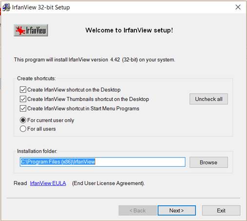
2. Now, choose where to install IrfanView and whether you want to create shortcuts. Click Next.
|
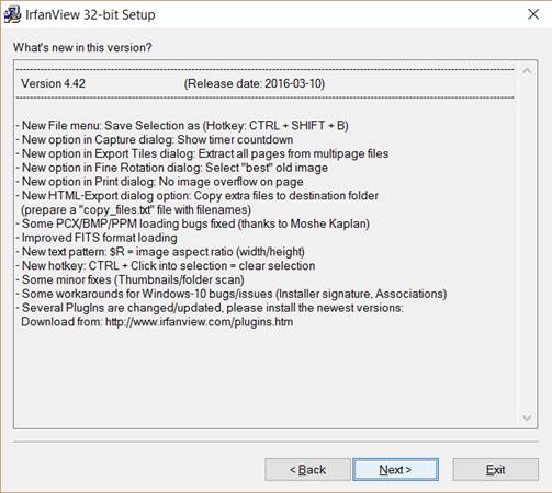
3. You can now see what’s new in the current version of the program. Click Next.
|
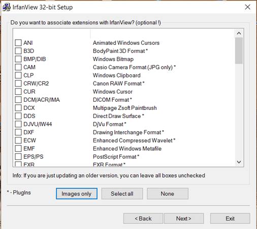
4. Then, you can choose (or leave unchecked) which filetypes you want to be associated with IrfanView (which ones will open in IrfanView when you open them from Windows Explorer). Click Next.
|
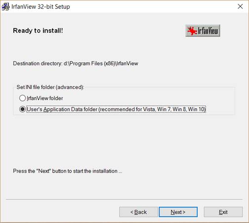
5. Choose where to save the INI file that has IrfanView’s configuration in it. Click Next.
|
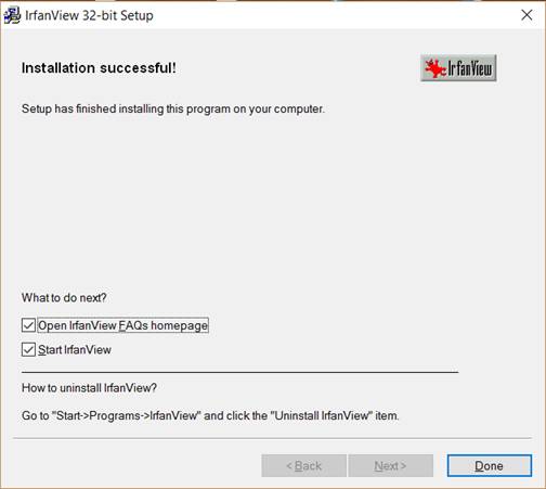
6. Now IrfanView installs. When it is installed, click Done.
How to open and find files in IrfanView
To open a file in IrfanView, once it’s launched:
|
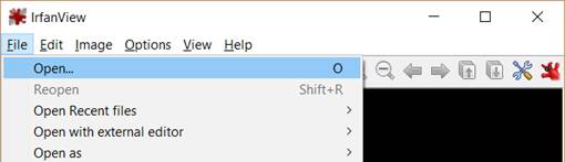
1. First, click File > Open. You can also click an icon with an open folder or just press O.
|
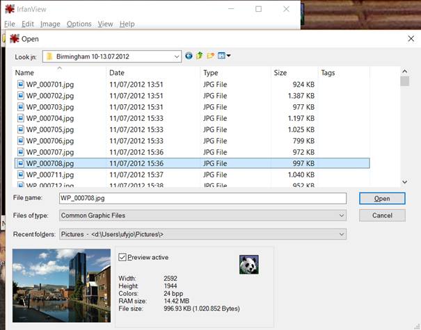
2. Now, go to the directory where the file is saved, select it, and click Open.
IrfanView will automatically read the list of files in the directory of the selected image. That way you can view other files from this folder by pressing left and right arrows on your keyboard or on the program’s taskbar.
|

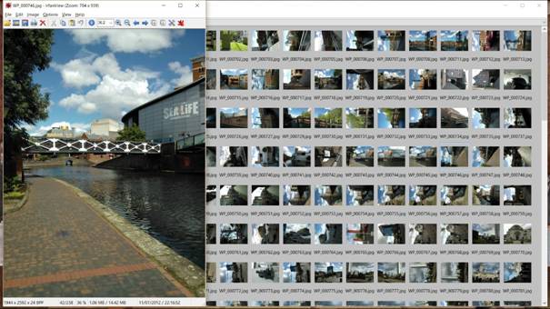
By selecting File > Thumbnails or pressing T you can go to the thumbnail view of the folder and easily explore your collections. To open any of those files, just double-click on it.
Search and find files in IrfanView
|
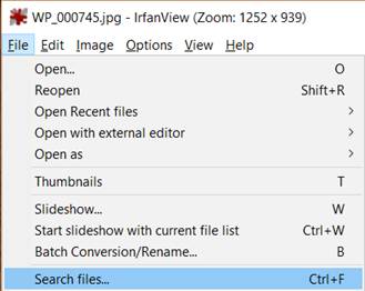
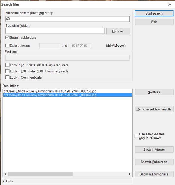
To search for files, go to File > Search files… or press Ctrl+F. In the dialog box, write what you look for. You can search in the filenames, EXIF data, IPTC data or comments. You can also change the directory. After you decided what to look for, press Start search. Select a file from the results list and press Show in Viewer.
How to send images with email using IrfanView
To send an image with email, you need to first install the email plugin from the IrfanView website.
1. Once you download the plugins installer, open it.
|
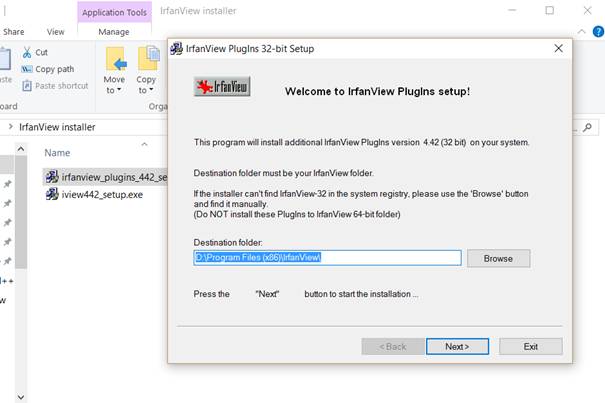
2. Then, make sure the IrfanView directory is correct. Click Next.
|
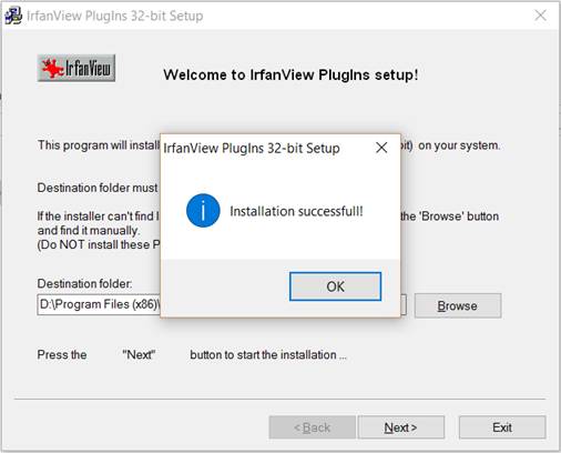
3. The plugins are now installed.
|
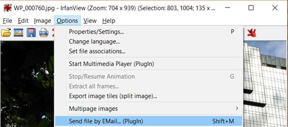
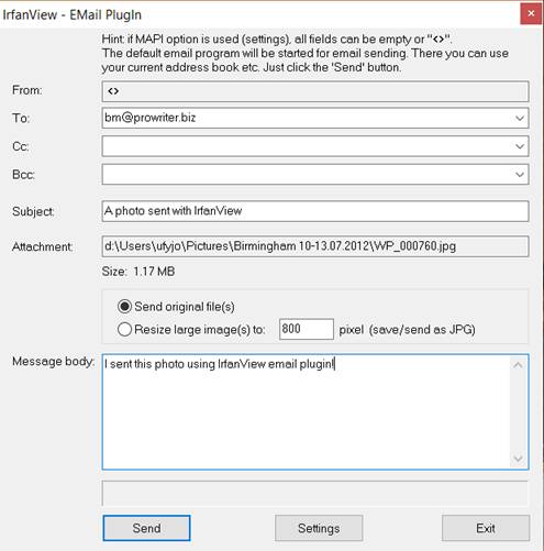
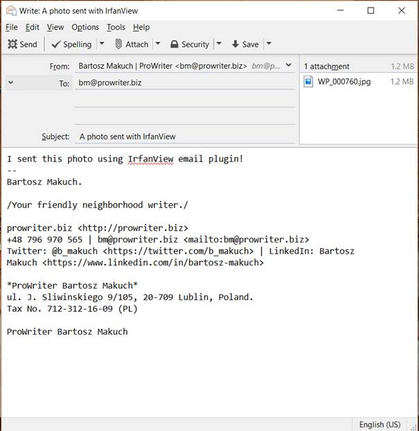
Select Options > Send file by EMail (PlugIn) or press Shift+M. Fill in the form and click Send. Your email manager will open and you just need to click Send again.
How to scan images using IrfanView
If you want to scan images directly to IrfanView:
|
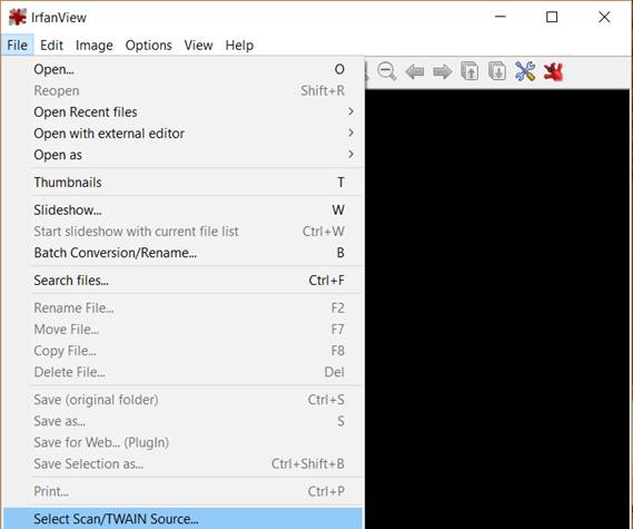
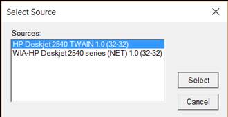
1. First, go to File > Select scan/TWAIN source.
|
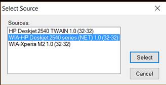
2. Choose the device from the list. Click Select. This time, let’s go with the WIA driver. It works well if you want to scan just one image at a time.
|
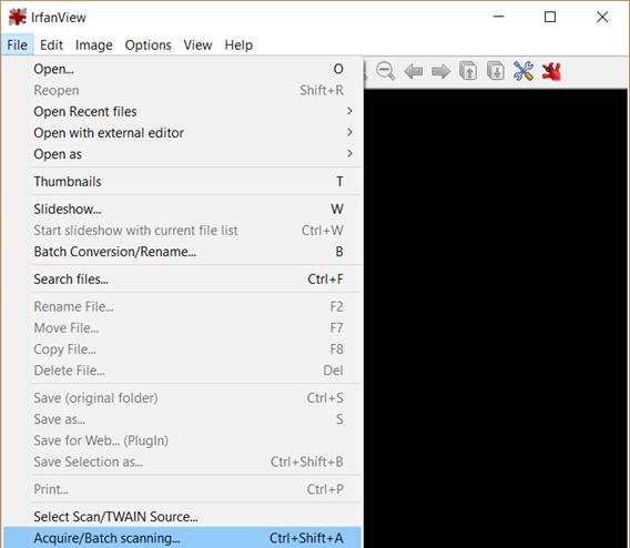
3. Then, go to File >Acquire/Batch scanning (or press Ctrl+Shift+A).
|
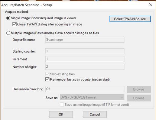
4. In the dialog box, click OK.
|
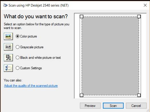
5. A window of your scanner manufacturer’s software will appear. Follow instructions to scan the image.
|

6. You can now edit and save your image.
If you want to scan multiple images at once:
1. First, we need to use the TWAIN driver. Go to File > Select scan/TWAIN source and select a TWAIN driver.
|
2. Then, go to File >Acquire/Batch scanning (or press Ctrl+Shift+A).
|
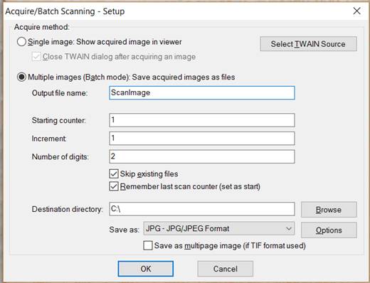
3. Select Multiple images (Batch mode) in the dialog box. You can change filenames and the destination folder. Click OK.
|
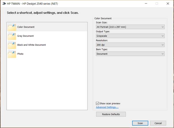
4. Choose image options and click Scan.
|
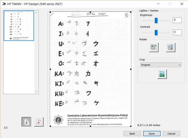
5. Click a plus icon to add pages.
6. When you finish scanning all the pages you need, click Done.
How to print images with IrfanView
|
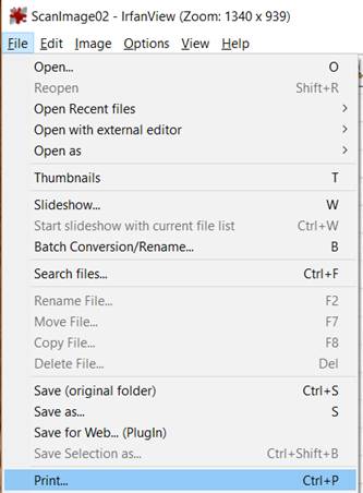
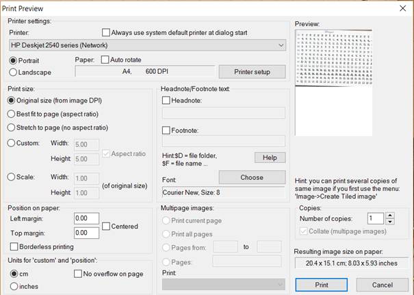
To print an image, go toFile > Print (or press Ctrl+P). You can adjust multiple print settings. To send the job to the printer, just press Print.
How to take screenshots with IrfanView
|
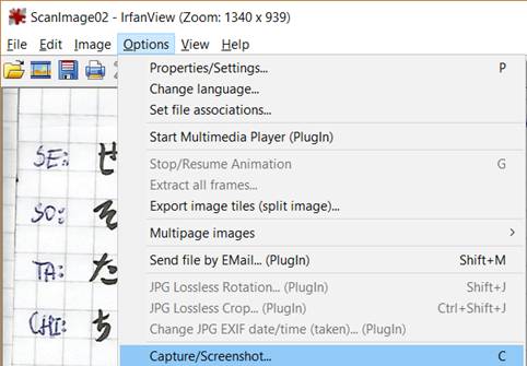
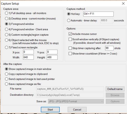
To take screenshots, go to Options > Capture/Screenshots (or press C). You can select a variety of options. When you set everything up, click Start.
|

For example, the settings shown above allow you to get screenshots of active windows and include the cursor. You just need to press Ctrl+F11. So, press it when you’re ready.
How to extract an icon from anexe or dll file with IrfanView
If you want to extract an icon from an exe or dll file:
|
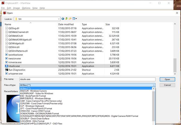
1. First,select All files (*.*) from the Files of type list in the Open dialog box.
2. Then, select the file you want to extract an icon from and click Open.
|
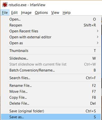

3. You can now safely save the icon to the format of your choice. Just go to File > Save as… (or just press S) and then select the directory and format of the icon. Click Save.
How to change IrfanView’s toolbar icons
|
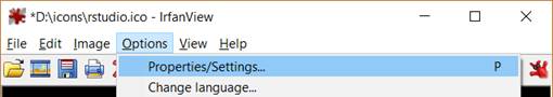
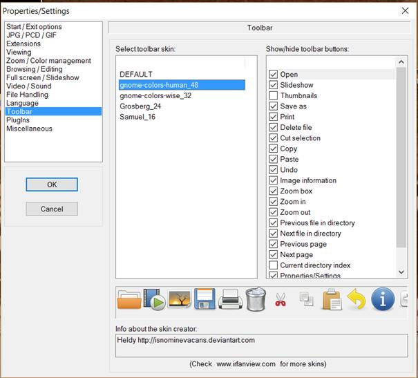
To change the look of IrfanView’s toolbar, go to Options > Properties/Settings (or press P). Select Toolbar and then select the skin you like most. Click OK. You can preview and download more skins from the IrfanView’s homepage.
How to manage which types of files IrfanView opens
|

You can manage which types of files IrfanView will open when you double-click on them in the Windows Explorer when you go to the Properties/Settings window and select the Extensions tab. NOTE: you must start IrfanView in ADMIN mode if you want to change file associations (use right mouse button click on IrfanView to start it in Admin mode).
What’s more?
So, there you have it. That’s all you need to know to start using IrfanView. To learn more about IrfanView’s options you can check out our guide to image editing.
JPEG
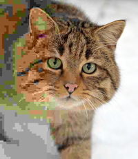 A photo of a European wildcat with the compression rate decreasing and hence quality increasing, from left to right | |
| Filename extension | , , , , |
|---|---|
| Internet media type | |
| Type code | [citation needed] |
| Uniform Type Identifier (UTI) | public.jpeg |
| Magic number | |
| Developed by | Joint Photographic Experts Group, IBM, Mitsubishi Electric, AT&T, Canon Inc.,[1]ITU-T Study Group 16 |
| Initial release | September 18, 1992; 28 years ago (1992-09-18) |
| Type of format | Lossyimage compressionformat |
| Standard | ITU-T T.81, ITU-T T.83, ITU-T T.84, ITU-T T.86, ISO/IEC 10918 |
| Website | www.jpeg.org/jpeg/ |
JPEG (/ˈdʒeɪpɛɡ/JAY-peg)[2] is a commonly used method of lossy compression for digital images, particularly for those images produced by digital photography. The degree of compression can be adjusted, allowing a selectable tradeoff between storage size and image quality. JPEG typically achieves 10:1 compression with little perceptible loss in image quality.[3] Since its introduction in 1992, JPEG has been the most widely used image compression standard in the world,[4][5] and the most widely used digital image format, with several billion JPEG images produced every day as of 2015.[6]
The term "JPEG" is an initialism/acronym for the Joint Photographic Experts Group, which created the standard in 1992. The basis for JPEG is the discrete cosine transform (DCT),[1] a lossy image compression technique that was first proposed by Nasir Ahmed in 1972.[7] JPEG was largely responsible for the proliferation of digital images and digital photos across the Internet, and later social media.[8]
JPEG compression is used in a number of image file formats. JPEG/Exif is the most common image format used by digital cameras and other photographic image capture devices; along with JPEG/JFIF, it is the most common format for storing and transmitting photographic images on the World Wide Web.[9] These format variations are often not distinguished, and are simply called JPEG.
The MIME media type for JPEG is image/jpeg, except in older Internet Explorer versions, which provides a MIME type of image/pjpeg when uploading JPEG images.[10] JPEG files usually have a filename extension of or . JPEG/JFIF supports a maximum image size of 65,535×65,535 pixels,[11] hence up to 4 gigapixels for an aspect ratio of 1:1. In 2000, the JPEG group introduced a format intended to be a successor, JPEG 2000, but it was unable to replace the original JPEG as the dominant image standard.[12]
History[edit]
Background[edit]
The original JPEG specification published in 1992 implements processes from various earlier research papers and patents cited by the CCITT (now ITU-T, via ITU-T Study Group 16) and Joint Photographic Experts Group.[1] The main basis for JPEG's lossy compression algorithm is the discrete cosine transform (DCT),[1][13] which was first proposed by Nasir Ahmed as an image compression technique in 1972.[7][13] Ahmed developed a practical DCT algorithm with T. Natarajan of Kansas State University and K. R. Rao of the University of Texas in 1973.[7] Their seminal 1974 paper[14] is cited in the JPEG specification, along with several later research papers that did further work on DCT, including a 1977 paper by Wen-Hsiung Chen, C.H. Smith and S.C. Fralick that described a fast DCT algorithm,[1][15] as well as a 1978 paper by N.J. Narasinha and S.C. Fralick, and a 1984 paper by B.G. Lee.[1] The specification also cites a 1984 paper by Wen-Hsiung Chen and W.K. Pratt as an influence on its quantization algorithm,[1][16] and David A. Huffman's 1952 paper for its Huffman coding algorithm.[1]
The JPEG specification cites patents from several companies. The following patents provided the basis for its arithmetic coding algorithm.[1]
- IBM
- U.S. Patent 4,652,856 – February 4, 1986 – Kottappuram M. A. Mohiuddin and Jorma J. Rissanen – Multiplication-free multi-alphabet arithmetic code
- U.S. Patent 4,905,297 – February 27, 1990 – G. Langdon, J.L. Mitchell, W.B. Pennebaker, and Jorma J. Rissanen – Arithmetic coding encoder and decoder system
- U.S. Patent 4,935,882 – June 19, 1990 – W.B. Pennebaker and J.L. Mitchell – Probability adaptation for arithmetic coders
- Mitsubishi Electric
- JP H02202267 (1021672) – January 21, 1989 – Toshihiro Kimura, Shigenori Kino, Fumitaka Ono, Masayuki Yoshida – Coding system
- JP H03247123 (2-46275) – February 26, 1990 – Fumitaka Ono, Tomohiro Kimura, Masayuki Yoshida, and Shigenori Kino – Coding apparatus and coding method
The JPEG specification also cites three other patents from IBM. Other companies cited as patent holders include AT&T (two patents) and Canon Inc.[1] Absent from the list is U.S. Patent 4,698,672, filed by Compression Labs' Wen-Hsiung Chen and Daniel J. Klenke in October 1986. The patent describes a DCT-based image compression algorithm, and would later be a cause of controversy in 2002 (see Patent controversy below).[17] However, the JPEG specification did cite two earlier research papers by Wen-Hsiung Chen, published in 1977 and 1984.[1]
JPEG standard[edit]
"JPEG" stands for Joint Photographic Experts Group, the name of the committee that created the JPEG standard and also other still picture coding standards. The "Joint" stood for ISO TC97 WG8 and CCITT SGVIII. Founded in 1986, the group developed the JPEG standard during the late 1980s. Among several transform coding techniques they examined, they selected the discrete cosine transform (DCT), as it was by far the most efficient practical compression technique. The group published the JPEG standard in 1992.[4]
In 1987, ISO TC 97 became ISO/IEC JTC1 and, in 1992, CCITT became ITU-T. Currently on the JTC1 side, JPEG is one of two sub-groups of ISO/IECJoint Technical Committee 1, Subcommittee 29, Working Group 1 (ISO/IEC JTC 1/SC 29/WG 1) – titled as Coding of still pictures.[18][19][20] On the ITU-T side, ITU-T SG16 is the respective body. The original JPEG Group was organized in 1986,[21] issuing the first JPEG standard in 1992, which was approved in September 1992 as ITU-T Recommendation T.81[22] and, in 1994, as ISO/IEC 10918-1.
The JPEG standard specifies the codec, which defines how an image is compressed into a stream of bytes and decompressed back into an image, but not the file format used to contain that stream.[23] The Exif and JFIF standards define the commonly used file formats for interchange of JPEG-compressed images.
JPEG standards are formally named as Information technology – Digital compression and coding of continuous-tone still images. ISO/IEC 10918 consists of the following parts:
| Part | ISO/IEC standard | ITU-T Rec. | First public release date | Latest amendment | Title | Description |
|---|---|---|---|---|---|---|
| Part 1 | ISO/IEC 10918-1:1994 | T.81 (09/92) | Sep 18, 1992 | Requirements and guidelines | ||
| Part 2 | ISO/IEC 10918-2:1995 | T.83 (11/94) | Nov 11, 1994 | Compliance testing | Rules and checks for software conformance (to Part 1). | |
| Part 3 | ISO/IEC 10918-3:1997 | T.84 (07/96) | Jul 3, 1996 | Apr 1, 1999 | Extensions | Set of extensions to improve the Part 1, including the Still Picture Interchange File Format (SPIFF).[25] |
| Part 4 | ISO/IEC 10918-4:1999 | T.86 (06/98) | Jun 18, 1998 | Jun 29, 2012 | Registration of JPEG profiles, SPIFF profiles, SPIFF tags, SPIFF colour spaces, APPn markers, SPIFF compression types and Registration Authorities (REGAUT) | methods for registering some of the parameters used to extend JPEG |
| Part 5 | ISO/IEC 10918-5:2013 | T.871 (05/11) | May 14, 2011 | JPEG File Interchange Format (JFIF) | A popular format which has been the de facto file format for images encoded by the JPEG standard. In 2009, the JPEG Committee formally established an Ad Hoc Group to standardize JFIF as JPEG Part 5.[26] | |
| Part 6 | ISO/IEC 10918-6:2013 | T.872 (06/12) | Jun 2012 | Application to printing systems | Specifies a subset of features and application tools for the interchange of images encoded according to the ISO/IEC 10918-1 for printing. | |
| Part 7 | ISO/IEC 10918-7:2019 | T.873 (05/19) | May 2019 | Digital compression and coding of continuous-tone still images | Provides reference software for the coding technology specified in Recommendation ITU-T T.81 - ISO/IEC 10918-1. While the reference implementations also provide an encoder, conformance testing of their encoding process is beyond the scope of this Specification. |
Ecma InternationalTR/98 specifies the JPEG File Interchange Format (JFIF); the first edition was published in June 2009.[27]
Patent controversy[edit]
In 2002, Forgent Networks asserted that it owned and would enforce patent rights on the JPEG technology, arising from a patent that had been filed on October 27, 1986, and granted on October 6, 1987: U.S. Patent 4,698,672 by Compression Labs' Wen-Hsiung Chen and Daniel J. Klenke.[17][28] While Forgent did not own Compression Labs at the time, Chen later sold Compression Labs to Forgent, before Chen went on to work for Cisco. This led to Forgent acquiring ownership over the patent.[17] Forgent's 2002 announcement created a furor reminiscent of Unisys' attempts to assert its rights over the GIF image compression standard.
The JPEG committee investigated the patent claims in 2002 and were of the opinion that they were invalidated by prior art,[29] a view shared by various experts.[17][30] The patent describes an image compression algorithm based on the discrete cosine transform (DCT),[17] a lossy image compression technique that originated from a 1974 paper by Nasir Ahmed, T. Natarajan and K. R. Rao.[1][13][14] Wen-Hsiung Chen further developed their DCT technique, describing a fast DCT algorithm in a 1977 paper with C.H. Smith and S.C. Fralick.[15][17] The 1992 JPEG specification cites both the 1974 Ahmed paper and the 1977 Chen paper for its DCT algorithm, as well as a 1984 paper by Chen and W.K. Pratt for its quantization algorithm.[1][16] Compression Labs was founded by Chen, and was the first company to commercialize DCT technology.[31] By the time Chen had filed his patent for a DCT-based image compression algorithm with Klenke in 1986, most of what would later become the JPEG standard had already been formulated in prior literature.[17] JPEG representative Richard Clark also claimed that Chen himself sat in one of the JPEG committees, but Forgent denied this claim.[17]
Between 2002 and 2004, Forgent was able to obtain about US$105 million by licensing their patent to some 30 companies. In April 2004, Forgent sued 31 other companies to enforce further license payments. In July of the same year, a consortium of 21 large computer companies filed a countersuit, with the goal of invalidating the patent. In addition, Microsoft launched a separate lawsuit against Forgent in April 2005.[32] In February 2006, the United States Patent and Trademark Office agreed to re-examine Forgent's JPEG patent at the request of the Public Patent Foundation.[33] On May 26, 2006 the USPTO found the patent invalid based on prior art. The USPTO also found that Forgent knew about the prior art, yet it intentionally avoided telling the Patent Office. This makes any appeal to reinstate the patent highly unlikely to succeed.[34]
Forgent also possesses a similar patent granted by the European Patent Office in 1994, though it is unclear how enforceable it is.[35]
As of October 27, 2006, the U.S. patent's 20-year term appears to have expired, and in November 2006, Forgent agreed to abandon enforcement of patent claims against use of the JPEG standard.[36]
The JPEG committee has as one of its explicit goals that their standards (in particular their baseline methods) be implementable without payment of license fees, and they have secured appropriate license rights for their JPEG 2000 standard from over 20 large organizations.
Beginning in August 2007, another company, Global Patent Holdings, LLC claimed that its patent (U.S. Patent 5,253,341) issued in 1993, is infringed by the downloading of JPEG images on either a website or through e-mail. If not invalidated, this patent could apply to any website that displays JPEG images. The patent was under reexamination by the U.S. Patent and Trademark Office from 2000–2007; in July 2007, the Patent Office revoked all of the original claims of the patent but found that an additional claim proposed by Global Patent Holdings (claim 17) was valid.[37] Global Patent Holdings then filed a number of lawsuits based on claim 17 of its patent.
In its first two lawsuits following the reexamination, both filed in Chicago, Illinois, Global Patent Holdings sued the Green Bay Packers, CDW, Motorola, Apple, Orbitz, Officemax, Caterpillar, Kraft and Peapod as defendants. A third lawsuit was filed on December 5, 2007 in South Florida against ADT Security Services, AutoNation, Florida Crystals Corp., HearUSA, MovieTickets.com, Ocwen Financial Corp. and Tire Kingdom, and a fourth lawsuit on January 8, 2008 in South Florida against the Boca Raton Resort & Club. A fifth lawsuit was filed against Global Patent Holdings in Nevada. That lawsuit was filed by Zappos.com, Inc., which was allegedly threatened by Global Patent Holdings, and sought a judicial declaration that the '341 patent is invalid and not infringed.
Global Patent Holdings had also used the '341 patent to sue or threaten outspoken critics of broad software patents, including Gregory Aharonian[38] and the anonymous operator of a website blog known as the "Patent Troll Tracker."[39] On December 21, 2007, patent lawyer Vernon Francissen of Chicago asked the U.S. Patent and Trademark Office to reexamine the sole remaining claim of the '341 patent on the basis of new prior art.[40]
On March 5, 2008, the U.S. Patent and Trademark Office agreed to reexamine the '341 patent, finding that the new prior art raised substantial new questions regarding the patent's validity.[41] In light of the reexamination, the accused infringers in four of the five pending lawsuits have filed motions to suspend (stay) their cases until completion of the U.S. Patent and Trademark Office's review of the '341 patent. On April 23, 2008, a judge presiding over the two lawsuits in Chicago, Illinois granted the motions in those cases.[42] On July 22, 2008, the Patent Office issued the first "Office Action" of the second reexamination, finding the claim invalid based on nineteen separate grounds.[43] On Nov. 24, 2009, a Reexamination Certificate was issued cancelling all claims.
Beginning in 2011 and continuing as of early 2013, an entity known as Princeton Digital Image Corporation,[44] based in Eastern Texas, began suing large numbers of companies for alleged infringement of U.S. Patent 4,813,056. Princeton claims that the JPEG image compression standard infringes the '056 patent and has sued large numbers of websites, retailers, camera and device manufacturers and resellers. The patent was originally owned and assigned to General Electric. The patent expired in December 2007, but Princeton has sued large numbers of companies for "past infringement" of this patent. (Under U.S. patent laws, a patent owner can sue for "past infringement" up to six years before the filing of a lawsuit, so Princeton could theoretically have continued suing companies until December 2013.) As of March 2013, Princeton had suits pending in New York and Delaware against more than 55 companies. General Electric's involvement in the suit is unknown, although court records indicate that it assigned the patent to Princeton in 2009 and retains certain rights in the patent.[45]
Typical usage[edit]
The JPEG compression algorithm operates at its best on photographs and paintings of realistic scenes with smooth variations of tone and color. For web usage, where reducing the amount of data used for an image is important for responsive presentation, JPEG's compression benefits make JPEG popular. JPEG/Exif is also the most common format saved by digital cameras.
However, JPEG is not well suited for line drawings and other textual or iconic graphics, where the sharp contrasts between adjacent pixels can cause noticeable artifacts. Such images are better saved in a lossless graphics format such as TIFF, GIF, or PNG.[46] The JPEG standard includes a lossless coding mode, but that mode is not supported in most products.
As the typical use of JPEG is a lossy compression method, which reduces the image fidelity, it is inappropriate for exact reproduction of imaging data (such as some scientific and medical imaging applications and certain technical image processing work).
JPEG is also not well suited to files that will undergo multiple edits, as some image quality is lost each time the image is recompressed, particularly if the image is cropped or shifted, or if encoding parameters are changed – see digital generation loss for details. To prevent image information loss during sequential and repetitive editing, the first edit can be saved in a lossless format, subsequently edited in that format, then finally published as JPEG for distribution.
JPEG compression[edit]
JPEG uses a lossy form of compression based on the discrete cosine transform (DCT). This mathematical operation converts each frame/field of the video source from the spatial (2D) domain into the frequency domain (a.k.a. transform domain). A perceptual model based loosely on the human psychovisual system discards high-frequency information, i.e. sharp transitions in intensity, and color hue. In the transform domain, the process of reducing information is called quantization. In simpler terms, quantization is a method for optimally reducing a large number scale (with different occurrences of each number) into a smaller one, and the transform-domain is a convenient representation of the image because the high-frequency coefficients, which contribute less to the overall picture than other coefficients, are characteristically small-values with high compressibility. The quantized coefficients are then sequenced and losslessly packed into the output bitstream. Nearly all software implementations of JPEG permit user control over the compression ratio (as well as other optional parameters), allowing the user to trade off picture-quality for smaller file size. In embedded applications (such as miniDV, which uses a similar DCT-compression scheme), the parameters are pre-selected and fixed for the application.
The compression method is usually lossy, meaning that some original image information is lost and cannot be restored, possibly affecting image quality. There is an optional lossless mode defined in the JPEG standard. However, this mode is not widely supported in products.
There is also an interlacedprogressive JPEG format, in which data is compressed in multiple passes of progressively higher detail. This is ideal for large images that will be displayed while downloading over a slow connection, allowing a reasonable preview after receiving only a portion of the data. However, support for progressive JPEGs is not universal. When progressive JPEGs are received by programs that do not support them (such as versions of Internet Explorer before Windows 7)[47] the software displays the image only after it has been completely downloaded.
Lossless editing[edit]
A number of alterations to a JPEG image can be performed losslessly (that is, without recompression and the associated quality loss) as long as the image size is a multiple of 1 MCU block (Minimum Coded Unit) (usually 16 pixels in both directions, for 4:2:0 chroma subsampling). Utilities that implement this include:
- and its GUI, Jpegcrop.
- using "JPG Lossless Crop (PlugIn)" and "JPG Lossless Rotation (PlugIn)", which require installing the JPG_TRANSFORM plugin.
- using "Lossless Crop to File" and "JPEG Lossless Rotate".
- using "JPEG lossless transformations".
- supports lossless rotation (but not lossless cropping) with its "Force lossless JPEG operations" option.
Blocks can be rotated in 90-degree increments, flipped in the horizontal, vertical and diagonal axes and moved about in the image. Not all blocks from the original image need to be used in the modified one.
The top and left edge of a JPEG image must lie on an 8 × 8 pixel block boundary, but the bottom and right edge need not do so. This limits the possible lossless crop operations, and also prevents flips and rotations of an image whose bottom or right edge does not lie on a block boundary for all channels (because the edge would end up on top or left, where – as aforementioned – a block boundary is obligatory).
Rotations where the image width and height not a multiple of 8 or 16 (depending upon the chroma subsampling), are not lossless. Rotating such an image causes the blocks to be recomputed which results in loss of quality.[48]
When using lossless cropping, if the bottom or right side of the crop region is not on a block boundary, then the rest of the data from the partially used blocks will still be present in the cropped file and can be recovered. It is also possible to transform between baseline and progressive formats without any loss of quality, since the only difference is the order in which the coefficients are placed in the file.
Furthermore, several JPEG images can be losslessly joined together, as long as they were saved with the same quality and the edges coincide with block boundaries.
JPEG files[edit]
The file format known as "JPEG Interchange Format" (JIF) is specified in Annex B of the standard. However, this "pure" file format is rarely used, primarily because of the difficulty of programming encoders and decoders that fully implement all aspects of the standard and because of certain shortcomings of the standard:
- Color space definition
- Component sub-sampling registration
- Pixel aspect ratio definition.
Several additional standards have evolved to address these issues. The first of these, released in 1992, was the JPEG File Interchange Format (or JFIF), followed in recent years by Exchangeable image file format (Exif) and ICCcolor profiles. Both of these formats use the actual JIF byte layout, consisting of different markers, but in addition, employ one of the JIF standard's extension points, namely the application markers: JFIF uses APP0, while Exif uses APP1. Within these segments of the file that were left for future use in the JIF standard and are not read by it, these standards add specific metadata.
Thus, in some ways, JFIF is a cut-down version of the JIF standard in that it specifies certain constraints (such as not allowing all the different encoding modes), while in other ways, it is an extension of JIF due to the added metadata. The documentation for the original JFIF standard states:[49]
- JPEG File Interchange Format is a minimal file format which enables JPEG bitstreams to be exchanged between a wide variety of platforms and applications. This minimal format does not include any of the advanced features found in the TIFF JPEG specification or any application specific file format. Nor should it, for the only purpose of this simplified format is to allow the exchange of JPEG compressed images.
Image files that employ JPEG compression are commonly called "JPEG files", and are stored in variants of the JIF image format. Most image capture devices (such as digital cameras) that output JPEG are actually creating files in the Exif format, the format that the camera industry has standardized on for metadata interchange. On the other hand, since the Exif standard does not allow color profiles, most image editing software stores JPEG in JFIF format, and also includes the APP1 segment from the Exif file to include the metadata in an almost-compliant way; the JFIF standard is interpreted somewhat flexibly.[50]
Strictly speaking, the JFIF and Exif standards are incompatible, because each specifies that its marker segment (APP0 or APP1, respectively) appear first. In practice, most JPEG files contain a JFIF marker segment that precedes the Exif header. This allows older readers to correctly handle the older format JFIF segment, while newer readers also decode the following Exif segment, being less strict about requiring it to appear first.
JPEG filename extensions[edit]
The most common filename extensions for files employing JPEG compression are and , though , and are also used. It is also possible for JPEG data to be embedded in other file types – TIFF encoded files often embed a JPEG image as a thumbnail of the main image; and MP3 files can contain a JPEG of cover art in the ID3v2 tag.
Color profile[edit]
Many JPEG files embed an ICC color profile (color space). Commonly used color profiles include sRGB and Adobe RGB. Because these color spaces use a non-linear transformation, the dynamic range of an 8-bit JPEG file is about 11 stops; see gamma curve.
Syntax and structure[edit]
A JPEG image consists of a sequence of segments, each beginning with a marker, each of which begins with a 0xFF byte, followed by a byte indicating what kind of marker it is. Some markers consist of just those two bytes; others are followed by two bytes (high then low), indicating the length of marker-specific payload data that follows. (The length includes the two bytes for the length, but not the two bytes for the marker.) Some markers are followed by entropy-coded data; the length of such a marker does not include the entropy-coded data. Note that consecutive 0xFF bytes are used as fill bytes for padding purposes, although this fill byte padding should only ever take place for markers immediately following entropy-coded scan data (see JPEG specification section B.1.1.2 and E.1.2 for details; specifically "In all cases where markers are appended after the compressed data, optional 0xFF fill bytes may precede the marker").
Within the entropy-coded data, after any 0xFF byte, a 0x00 byte is inserted by the encoder before the next byte, so that there does not appear to be a marker where none is intended, preventing framing errors. Decoders must skip this 0x00 byte. This technique, called byte stuffing (see JPEG specification section F.1.2.3), is only applied to the entropy-coded data, not to marker payload data. Note however that entropy-coded data has a few markers of its own; specifically the Reset markers (0xD0 through 0xD7), which are used to isolate independent chunks of entropy-coded data to allow parallel decoding, and encoders are free to insert these Reset markers at regular intervals (although not all encoders do this).
| Short name | Bytes | Payload | Name | Comments |
|---|---|---|---|---|
| SOI | 0xFF, 0xD8 | none | Start Of Image | |
| SOF0 | 0xFF, 0xC0 | variable size | Start Of Frame (baseline DCT) | Indicates that this is a baseline DCT-based JPEG, and specifies the width, height, number of components, and component subsampling (e.g., 4:2:0). |
| SOF2 | 0xFF, 0xC2 | variable size | Start Of Frame (progressive DCT) | Indicates that this is a progressive DCT-based JPEG, and specifies the width, height, number of components, and component subsampling (e.g., 4:2:0). |
| DHT | 0xFF, 0xC4 | variable size | Define Huffman Table(s) | Specifies one or more Huffman tables. |
| DQT | 0xFF, 0xDB | variable size | Define Quantization Table(s) | Specifies one or more quantization tables. |
| DRI | 0xFF, 0xDD | 4 bytes | Define Restart Interval | Specifies the interval between RSTn markers, in Minimum Coded Units (MCUs). This marker is followed by two bytes indicating the fixed size so it can be treated like any other variable size segment. |
| SOS | 0xFF, 0xDA | variable size | Start Of Scan | Begins a top-to-bottom scan of the image. In baseline DCT JPEG images, there is generally a single scan. Progressive DCT JPEG images usually contain multiple scans. This marker specifies which slice of data it will contain, and is immediately followed by entropy-coded data. |
| RSTn | 0xFF, 0xDn (n=0..7) | none | Restart | Inserted every r macroblocks, where r is the restart interval set by a DRI marker. Not used if there was no DRI marker. The low three bits of the marker code cycle in value from 0 to 7. |
| APPn | 0xFF, 0xEn | variable size | Application-specific | For example, an Exif JPEG file uses an APP1 marker to store metadata, laid out in a structure based closely on TIFF. |
| COM | 0xFF, 0xFE | variable size | Comment | Contains a text comment. |
| EOI | 0xFF, 0xD9 | none | End Of Image |
There are other Start Of Frame markers that introduce other kinds of JPEG encodings.
Since several vendors might use the same APPn marker type, application-specific markers often begin with a standard or vendor name (e.g., "Exif" or "Adobe") or some other identifying string.
At a restart marker, block-to-block predictor variables are reset, and the bitstream is synchronized to a byte boundary. Restart markers provide means for recovery after bitstream error, such as transmission over an unreliable network or file corruption. Since the runs of macroblocks between restart markers may be independently decoded, these runs may be decoded in parallel.
JPEG codec example[edit]
Although a JPEG file can be encoded in various ways, most commonly it is done with JFIF encoding. The encoding process consists of several steps:
- The representation of the colors in the image is converted to Y′CBCR, consisting of one luma component (Y'), representing brightness, and two chroma components, (CB and CR), representing color. This step is sometimes skipped.
- The resolution of the chroma data is reduced, usually by a factor of 2 or 3. This reflects the fact that the eye is less sensitive to fine color details than to fine brightness details.
- The image is split into blocks of 8×8 pixels, and for each block, each of the Y, CB, and CR data undergoes the discrete cosine transform (DCT). A DCT is similar to a Fourier transform in the sense that it produces a kind of spatial frequency spectrum.
- The amplitudes of the frequency components are quantized. Human vision is much more sensitive to small variations in color or brightness over large areas than to the strength of high-frequency brightness variations. Therefore, the magnitudes of the high-frequency components are stored with a lower accuracy than the low-frequency components. The quality setting of the encoder (for example 50 or 95 on a scale of 0–100 in the Independent JPEG Group's library[52]) affects to what extent the resolution of each frequency component is reduced. If an excessively low quality setting is used, the high-frequency components are discarded altogether.
- The resulting data for all 8×8 blocks is further compressed with a lossless algorithm, a variant of Huffman encoding.
The decoding process reverses these steps, except the quantization because it is irreversible. In the remainder of this section, the encoding and decoding processes are described in more detail.
Encoding[edit]
Many of the options in the JPEG standard are not commonly used, and as mentioned above, most image software uses the simpler JFIF format when creating a JPEG file, which among other things specifies the encoding method. Here is a brief description of one of the more common methods of encoding when applied to an input that has 24 bits per pixel (eight each of red, green, and blue). This particular option is a lossy data compression method.
Color space transformation[edit]
First, the image should be converted from RGB into a different color space called Y′CBCR (or, informally, YCbCr). It has three components Y', CB and CR: the Y' component represents the brightness of a pixel, and the CB and CR components represent the chrominance (split into blue and red components). This is basically the same color space as used by digital color television as well as digital video including video DVDs, and is similar to the way color is represented in analog PAL video and MAC (but not by analog NTSC, which uses the YIQ color space). The Y′CBCR color space conversion allows greater compression without a significant effect on perceptual image quality (or greater perceptual image quality for the same compression). The compression is more efficient because the brightness information, which is more important to the eventual perceptual quality of the image, is confined to a single channel. This more closely corresponds to the perception of color in the human visual system. The color transformation also improves compression by statistical decorrelation.
A particular conversion to Y′CBCR is specified in the JFIF standard, and should be performed for the resulting JPEG file to have maximum compatibility. However, some JPEG implementations in "highest quality" mode do not apply this step and instead keep the color information in the RGB color model,[53] where the image is stored in separate channels for red, green and blue brightness components. This results in less efficient compression, and would not likely be used when file size is especially important.
Downsampling[edit]
Due to the densities of color- and brightness-sensitive receptors in the human eye, humans can see considerably more fine detail in the brightness of an image (the Y' component) than in the hue and color saturation of an image (the Cb and Cr components). Using this knowledge, encoders can be designed to compress images more efficiently.
The transformation into the Y′CBCR color model enables the next usual step, which is to reduce the spatial resolution of the Cb and Cr components (called "downsampling" or "chroma subsampling"). The ratios at which the downsampling is ordinarily done for JPEG images are 4:4:4 (no downsampling), 4:2:2 (reduction by a factor of 2 in the horizontal direction), or (most commonly) 4:2:0 (reduction by a factor of 2 in both the horizontal and vertical directions). For the rest of the compression process, Y', Cb and Cr are processed separately and in a very similar manner.
Block splitting[edit]
After subsampling, each channel must be split into 8×8 blocks. Depending on chroma subsampling, this yields Minimum Coded Unit (MCU) blocks of size 8×8 (4:4:4 – no subsampling), 16×8 (4:2:2), or most commonly 16×16 (4:2:0). In video compression MCUs are called macroblocks.
If the data for a channel does not represent an integer number of blocks then the encoder must fill the remaining area of the incomplete blocks with some form of dummy data. Filling the edges with a fixed color (for example, black) can create ringing artifacts along the visible part of the border; repeating the edge pixels is a common technique that reduces (but does not necessarily completely eliminate) such artifacts, and more sophisticated border filling techniques can also be applied.
Discrete cosine transform[edit]

Next, each 8×8 block of each component (Y, Cb, Cr) is converted to a frequency-domain representation, using a normalized, two-dimensional type-II discrete cosine transform (DCT), see Citation 1 in discrete cosine transform. The DCT is sometimes referred to as "type-II DCT" in the context of a family of transforms as in discrete cosine transform, and the corresponding inverse (IDCT) is denoted as "type-III DCT".
As an example, one such 8×8 8-bit subimage might be:
What’s New in the IrfanView V3.92 serial key or number?
Screen Shot
System Requirements for IrfanView V3.92 serial key or number
- First, download the IrfanView V3.92 serial key or number
-
You can download its setup from given links:

IrfanView V3.92 serial key or number & Software

IrfanView V3.92 serial key or number& Crack