
1Stop Organizer v1.0 serial key or number

1Stop Organizer v1.0 serial key or number
Cisco 2500 Series Wireless Controller Getting Started Guide
Table of Contents
Cisco 2500 Series Wireless Controller Getting Started Guide
About This Guide
FCC Safety Compliance Statement
Safety Information
Safety Considerations
Introduction to the Controller
Unpacking and Preparing the Controller for Operation
Package Contents
Required Tools and Information
Initial System Configuration Information
Configuring Management Interface
Choosing a Physical Location
Installing the Controller
Mounting the Controller
Mounting the Controller on a Desktop or Shelf
Mounting the Controller on a Wall (Rack-Mount Brackets)
Mounting the Controller on a Wall (Mounting Screws)
Mounting the Controller in a Rack
Connecting the Controller Console Port
Securing the Power Adapter Cable
Installing a Security Lock
Running the Bootup Script and Power-On Self Test
Using the Startup Wizard
Logging into the Controller
Connecting to the Network
Connecting Access Points
Checking the Controller LEDs
Using the Reset Button
What’s New in Cisco Product Documentation
Translated Safety Warnings
Statement 1071—Warning Definition
Statement 1015—Battery Handling
Statement 1024—Ground Conductor
Statement 1040—Product Disposal
Statement 371—Power Cable and AC Adapter
Statement 157—VCCI Compliance for Class B Equipment
Cisco 2500 Series Wireless Controller
Getting Started Guide
First Published: May 2011
About This Guide
This guide is designed to help y192.0.2.1ou install and minimally configure your Cisco 2504 Wireless Controller (2504 controller), which is part of the Cisco 2500 Series Wireless Controllers.
FCC Safety Compliance Statement
This equipment has been tested and found to comply with the limits for a Class B digital device, pursuant to Part 15 of the FCC Rules. These limits are designed to provide reasonable protection against harmful interference in a residential installation. This equipment generates, uses, and can radiate radio frequency energy and, if not installed and used in accordance with the instructions, may cause harmful interference to radio communications. However, there is no guarantee that interference will not occur in a particular installation. If this equipment does cause harmful interference to radio or television reception, which can be determined by turning the equipment off and on.
Try to correct the interference by one or more of the following measures:
- Reorient or relocate the receiving antenna.
- Increase the separation between the equipment and receiver.
- Connect the equipment to an outlet on a circuit different from that to which the receiver is connected.
- Consult the dealer or an experienced radio/TV technician for help. (cfr reference 15.105)
Safety Information
Safety warnings appear throughout this guide in procedures that may harm you if performed incorrectly. A warning symbol precedes each warning statement. The warnings below are general warnings that are applicable to the entire guide. Translated versions of the safety warnings in this guide are provided in the “Translated Safety Warnings” section.

Warning![]() This warning symbol means danger. You are in a situation that could cause bodily injury. Before you work on any equipment, be aware of the hazards involved with electrical circuitry and be familiar with standard practices for preventing accidents. Use the statement number provided at the end of each warning to locate its translation in the translated safety warnings that accompanied this device. Statement 1071
This warning symbol means danger. You are in a situation that could cause bodily injury. Before you work on any equipment, be aware of the hazards involved with electrical circuitry and be familiar with standard practices for preventing accidents. Use the statement number provided at the end of each warning to locate its translation in the translated safety warnings that accompanied this device. Statement 1071
SAVE THESE INSTRUCTIONS
Warning![]() There is the danger of explosion if the battery is replaced incorrectly. Replace the battery only with the same or equivalent type recommended by the manufacturer. Dispose of used batteries according to the manufacturer’s instructions. Statement 1015
There is the danger of explosion if the battery is replaced incorrectly. Replace the battery only with the same or equivalent type recommended by the manufacturer. Dispose of used batteries according to the manufacturer’s instructions. Statement 1015
Warning![]() This equipment must be grounded. Never defeat the ground conductor or operate the equipment in the absence of a suitably installed ground conductor. Contact the appropriate electrical inspection authority or an electrician if you are uncertain that suitable grounding is available. Statement 1024
This equipment must be grounded. Never defeat the ground conductor or operate the equipment in the absence of a suitably installed ground conductor. Contact the appropriate electrical inspection authority or an electrician if you are uncertain that suitable grounding is available. Statement 1024
Warning![]() Ultimate disposal of this product should be handled according to all national laws and regulations. Statement 1040
Ultimate disposal of this product should be handled according to all national laws and regulations. Statement 1040
Safety Considerations
- Verify that the ambient temperature remains between 32 to 104° F (0 to 40° C), taking into account the elevated temperatures when installed in a rack or enclosed space.
- When multiple 2504 controllers are mounted in an equipment rack, be sure that the power source is sufficiently rated to safely run all the equipment in the rack (input: 100 to 240 VAC, 50–60 Hz, output: 80 W per controller).
- Verify the integrity of the electrical ground before installing the controller.
Introduction to the Controller
The 2504 controller works in conjunction with Cisco lightweight access points and the Cisco Wireless Control System (WCS) to provide system-wide wireless LAN functions. As a component of the Cisco Unified Wireless Network (CUWN), the 2504 controller provides real-time communication between wireless access points and other devices to deliver centralized security policies, guest access, Wireless Intrusion Prevention System (WIPS), context-aware (location), award-winning RF management, quality of services for mobility services such as voice and video, and OEAP support for the Teleworker solution.
The 2504 controllers supports up to 50 lightweight access points in increments of 5 access points with a minimum of 5 access points, making it a cost-effective solution for retail, enterprise branches, and small and medium-sized businesses. The 2504 controller comes with four 4 Gigabit Ethernet ports.
The 2504 controller offers robust coverage with 802.11 a/b/g and delivers unprecedented reliability using 802.11n with Cisco Next-Generation Wireless Solutions and Cisco Enterprise Wireless Mesh.
To best use this guide, you should have already designed the wireless topology of your network and have a working knowledge of how controllers function in a wireless LAN network.

Note![]() For Cisco 2504 WLC, mobility configuration that is part of the WLAN configuration is not uploaded to the config file.
For Cisco 2504 WLC, mobility configuration that is part of the WLAN configuration is not uploaded to the config file.
Figure 1 shows a 2504 controller network topology and network connections, showing the medium dependent interface (MDI) Ethernet cables required. The controller has an auto MDI feature, so you can use straight-through or crossover cables.
Figure 1 Typical Controller Topology and Network Connections
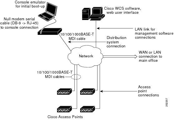
Figure 2 shows the front panel and location of the ports and light-emitting diodes (LEDs) for the 2504 controller. Table 1 describes the components of the front panel.
Note![]() It is expected that there will be small variations in LED color intensity and hue from unit to unit. This is within the normal range of the LED manufacturer’s specifications and is not a defect.
It is expected that there will be small variations in LED color intensity and hue from unit to unit. This is within the normal range of the LED manufacturer’s specifications and is not a defect.
Figure 2 Front Panel and LEDs
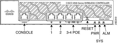
Table 1 WLC2504 Front Panel Component Descriptions
CONSOLE | CPU console port | The CPU console port is an RS-232 port that supports a RJ-45 connector. At boot-up the controller configures the RS-232 port as a console port with default settings of 9600, N, 8, 1. The boot-loader supports baud rates of 1200, 2400, 4800, 9600, 19200, 38400, 57600, and 115200. A default baud-rate recovery mechanism is not available; however the bootloader ensures that the stored baud rate setting matches one of the allowed values before setting the baud rate. If a nonstandard value is detected the baud rate will default to 9600. |
1 | GigE port and LED | The Gigabit Ethernet port is an RJ-45 connector form-factor. This port is designed so that 1500 VAC rms isolation (per the 802.3 specification) is met between chassis ground and any 48V/Ethernet signal. LED description:
|
2 | GigE port and LED | The Gigabit Ethernet port is an RJ-45 connector form-factor. This port is designed so that 1500 VAC rms isolation (per the 802.3 specification) is met between chassis ground and any 48V/Ethernet signal. LED description:
|
3 & 4 POE | GigE Power-over-Ethernet (POE) ports | The Gigabit POE ports are RJ-45 connector form-factor. They provide a I2C communications channel between the PSE controller and host CPU TWSI bus #1. This interface supports the proper voltage isolation as defined by 802.3. The POE controller is configured to I2C address 0x40/41 (0100 000r/w). The POE controller reset is driven from system reset. If software needs to reset the POE controller, it can do so over I2C. LED description:
Note The ports can be used for infra-switch connection using multiple an AP-Manager or data interface. |
RESET | Reset button | Pushing the Reset button reboots the system. |
PWR | Power LED | The power LED light is on when all the power conversion circuits are running normally. LED description:
|
SYS | System LED | The system LED determines if the system is powered up. LED description:
|
ALM | Alarm LED | The alarm LED determines a status or error occurred. The status or error is posted on the console screen. LED description:
|

Note![]() Wait at least 20 seconds before reconnecting an access point to the controller. Otherwise, the controller may fail to detect the device.
Wait at least 20 seconds before reconnecting an access point to the controller. Otherwise, the controller may fail to detect the device.
Note![]() Precautions for the direct AP connection: Do not configure interfaces on the physical ports, if AP is connected to the port. If an interface is configured on the port where AP is connected, the behavior is undefined. If the physical ports are configured, remove it and reload the controller.
Precautions for the direct AP connection: Do not configure interfaces on the physical ports, if AP is connected to the port. If an interface is configured on the port where AP is connected, the behavior is undefined. If the physical ports are configured, remove it and reload the controller.
Figure 3 shows the back panel and identifies its components. Table 2 describes the back panel components.
Figure 3 Controller Back Panel and Components
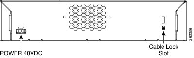
Table 2 Controller Back Panel and Component Descriptions
POWER 48VDC | The 48 V input power is provided via an external AC/DC adapter. Power is provided to the system board from the 48 VDC input. There is enough power available to power the system board plus two 802.3af PoE devices. Note The Cisco 2106 power adapter is not compatible with a 2504 controller. |
Cable Lock slot | Security locking slot. |
Unpacking and Preparing the Controller for Operation
Follow these steps to unpack the 2504 controller and prepare it for operation:
Step 1![]() Open the shipping container and carefully remove the contents.
Open the shipping container and carefully remove the contents.
Step 2![]() Return all packing materials to the shipping container and save it.
Return all packing materials to the shipping container and save it.
Step 3![]() Ensure that all items listed in the “Package Contents” section are included in the shipment. Check each item for damage. If any item is damaged or missing, notify your authorized Cisco sales representative.
Ensure that all items listed in the “Package Contents” section are included in the shipment. Check each item for damage. If any item is damaged or missing, notify your authorized Cisco sales representative.
Package Contents
Each 2504 controller package contains the following items:
- One Cisco 2504 Wireless Controller.
- One Power supply and power cord (power cord option configurable).
- Cisco 2504 Wireless Controller software pre-loaded on the controller (software option configurable).
- Optional licenses will be pre-installed on controller at factory, if selected.
- Two Number 6 Phillips pan-head screws for mounting the controller on a desk, shelf, or wall.
- Two wall anchors.
- Strain relief clip and screw.
- Optional hardware will be included, if selected.
Required Tools and Information
You will need the following tools and information before you can install the controller:
- Wireless controller hardware
–![]() Controller with factory-supplied power cord and mounting hardware
Controller with factory-supplied power cord and mounting hardware
–![]() Network, operating system service network, and access point cables as required
Network, operating system service network, and access point cables as required
- Command-line interface (CLI) console
–![]() VT-100 terminal emulator on CLI console (PC, laptop, or palmtop)
VT-100 terminal emulator on CLI console (PC, laptop, or palmtop)
–![]() Null modem serial cable to connect CLI console and controller
Null modem serial cable to connect CLI console and controller
- Local TFTP server (required for downloading operating system software updates). Cisco uses an integral TFTP server. This means that third-party TFTP servers cannot run on the same workstation as the Cisco WCS because Cisco WCS and third-party TFTP servers use the same communication port.
Initial System Configuration Information
Obtain the following initial configuration parameters from your wireless LAN or network administrator:
- A system (controller name), such as controller. The system name can contain up to 32 printable ASCII characters.
- An administrative username and password, which can contain up to 24 printable ASCII characters.
Note![]() You must enter a username and password and the configured username and password cannot be the same.
You must enter a username and password and the configured username and password cannot be the same.
- A management interface (DS Port or network interface port) IP address, such as 10.40.0.4.
- A management interface netmask address, such as 255.255.255.0.
- A management interface default router IP address, such as 10.40.0.5.
- A VLAN identifier if the management interface is assigned to a VLAN, such as 40 or 0 for an untagged VLAN.
- A management interface port, such as 1.
- A management interface DHCP server IP address, such as 10.40.0.6 (the IP address of the default DHCP server that will supply IP addresses to clients and the management interface.
- A virtual gateway IP address (a fictitious, unassigned IP address, such as 192.0.2.1, used by all Cisco wireless controller Layer 3 security and mobility managers).
- A Cisco wireless controller mobility or RF group name, such as rfgrp40 if required. An RF group name can contain up to 19 printable ASCII characters.
- An 802.11 network name (SSID), such as wlan1. An SSID can contain up to 32 printable, case-sensitive ASCII characters.
- DHCP bridging
- Whether or not to allow static IP addresses from clients, either Yes or No.
–![]() Yes is more convenient, but has lower security (session can be hijacked).
Yes is more convenient, but has lower security (session can be hijacked).
–![]() No is less convenient, but has higher security and works well for Windows XP devices.
No is less convenient, but has higher security and works well for Windows XP devices.
- RADIUS server IP address, communications port, and secret if you are configuring a RADIUS server, such as 10.40.0.3, 1812, and mysecretcode.
- The country code for this installation. Enter help to see a list or refer to the Cisco Wireless LAN Controller Configuration Guide for country code information. This guide is available at cisco.com.
- Status of the 802.11a, 802.11b, 802.11g, or 802.11n networks, either enabled or disabled.
- Status of Radio Resource Management (RRM), either enabled or disabled.
Configuring Management Interface
When you save the controller's configuration, the controller stores it in XML format in flash memory. Controller software release 5.2 or later releases enable you to easily read and modify the configuration file by converting it to CLI format. When you upload the configuration file to a TFTP/FTP/SFTP server, the controller initiates the conversion from XML to CLI. You can then read or edit the configuration file in a CLI format on the server. When you are finished, you download the file back to the controller, where it is reconverted to an XML format and saved.
The controller does not support the uploading and downloading of port configuration CLI commands. If you want to configure the controller ports, enter these commands:
- config port linktrap {port | all} {enable | disable}-Enables or disables the up and down link traps for a specific controller port or for all ports.
- configport adminmode {port | all} {enable |disable}-Enables or disables the administrative mode for a specific controller port or for all ports.
The management interface is the default interface for in-band management of the controller and connectivity to enterprise services such as AAA servers. It is also used for communications between the controller and access points. The management interface has the only consistently “pingable” in-band interface IP address on the controller. You can access the GUI of the controller by entering the management interface IP address of the controller in the address field of either Internet Explorer or Mozilla Firefox browser.
Following are the steps to configure the management interface:
Step 1![]() Enter the show interface detailed management command to view the current management interface settings.
Enter the show interface detailed management command to view the current management interface settings.
Note![]() The management interface uses the controller’s factory-set distribution system MAC address.
The management interface uses the controller’s factory-set distribution system MAC address.
Step 2![]() Enter the config wlan disable wlan-number command to disable each WLAN that uses the management interface for distribution system communication.
Enter the config wlan disable wlan-number command to disable each WLAN that uses the management interface for distribution system communication.
Step 3![]() Enter these commands to define the management interface:
Enter these commands to define the management interface:
–![]() config interface address management ip-addr ip-netmask gateway
config interface address management ip-addr ip-netmask gateway
–![]() config interface quarantine vlan management vlan_id
config interface quarantine vlan management vlan_id
Note![]() Use the config interface quarantine vlan management vlan_id command to configure a quarantine VLAN on the management interface.
Use the config interface quarantine vlan management vlan_id command to configure a quarantine VLAN on the management interface.
–![]() config interface vlan management {vlan-id | 0}
config interface vlan management {vlan-id | 0}
Note![]() Enter 0 for an untagged VLAN or a nonzero value for a tagged VLAN. We recommend using tagged VLANs for the management interface.
Enter 0 for an untagged VLAN or a nonzero value for a tagged VLAN. We recommend using tagged VLANs for the management interface.
–![]() config interface port management physical-ds-port-number
config interface port management physical-ds-port-number
–![]() config interface dhcp management ip-address-of-primary-dhcp-server [ip-address-of-secondary-dhcp-server]
config interface dhcp management ip-address-of-primary-dhcp-server [ip-address-of-secondary-dhcp-server]
–![]() config interface acl management access-control-list-name
config interface acl management access-control-list-name
Step 4![]() Enter the save config command.
Enter the save config command.
Step 5![]() Enter the show interface detailed management command to verify that your changes have been saved.
Enter the show interface detailed management command to verify that your changes have been saved.
Step 6![]() If you made any changes to the management interface, enter the reset system command to rebo ot the controller in order for the changes to take effect.
If you made any changes to the management interface, enter the reset system command to rebo ot the controller in order for the changes to take effect.
See Cisco Wireless LAN Controller Configuration Guide for more information.
Choosing a Physical Location
You can install the controller almost anywhere, but it is more secure and reliable if you install it in a secure equipment room or wiring closet. For maximum reliability, mount the controller while following these guidelines:
- Make sure you can reach the controller and all cables attached to it.
- Make sure that water or excessive moisture cannot get into the controller.
- Make sure that airflow through the controller is not obstructed. Leave at least 4 in. (10 cm) clear on both sides and rear of the controller.
- Verify that the ambient temperature remains between 32 to 104° F (0 to 40° C).
- Make sure that the controller is within 328 ft. (100 m) of equipment connected to the 10/100/1000 Mb/s Ethernet ports.
- Make sure that the power cord can reach a 100 to 240 VAC grounded electrical outlet.
Installing the Controller
This section includes the following installation procedures:
Mounting the Controller
This section includes the following mounting procedures:
Mounting the Controller on a Desktop or Shelf
Before mounting the controller on a desktop or shelf, install the rubber feet located in accessory kit shipped with the controller.
To install the rubber feet to the controller, follow these steps:
Step 1![]() Locate the adhesive strip with the rubber feet in the mounting-kit envelope.
Locate the adhesive strip with the rubber feet in the mounting-kit envelope.
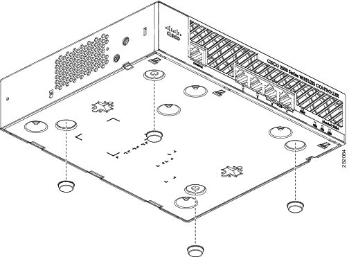
Step 2![]() Remove the four rubber feet from the adhesive strip and attach the feet to the recessed areas on the bottom of the unit as shown in Figure 4.
Remove the four rubber feet from the adhesive strip and attach the feet to the recessed areas on the bottom of the unit as shown in Figure 4.
Note![]() We strongly recommend that you attach the rubber feet. Doing so helps prevent airflow restriction and overheating.
We strongly recommend that you attach the rubber feet. Doing so helps prevent airflow restriction and overheating.
Figure 4 Installing the Rubber Feet on the Bottom of the Controller
Step 3![]() Place the switch on the table or shelf near an AC power source.
Place the switch on the table or shelf near an AC power source.
Note![]() Allow 3 inches of space around the controller ventilation openings to prevent airflow restriction and overheating.
Allow 3 inches of space around the controller ventilation openings to prevent airflow restriction and overheating.
Step 4![]() After the controller is mounted on a shelf or desk, perform the following tasks to complete the installation:
After the controller is mounted on a shelf or desk, perform the following tasks to complete the installation:
Step 5![]() For configuration instructions about using the CLI setup program, see the “Running the Bootup Script and Power-On Self Test” section.
For configuration instructions about using the CLI setup program, see the “Running the Bootup Script and Power-On Self Test” section.
Mounting the Controller on a Wall (Rack-Mount Brackets)
The controller can be mounted on a wall using an optional rack-mount bracket kit that is not included with the controller. You can order a kit with 19-inch rack mounting brackets and hardware from Cisco. The kit part number is AIR-CT2504-RMNT.
Warning![]() Read the wall-mounting carefully before beginning installation. Failure to use the correct hardware or to follow the correct procedures could result in a hazardous situation to people and damage to the system. Statement 378
Read the wall-mounting carefully before beginning installation. Failure to use the correct hardware or to follow the correct procedures could result in a hazardous situation to people and damage to the system. Statement 378
To mount the controller on a wall using rack-mount brackets, follow these steps:
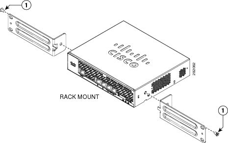
Step 1![]() Attach the 19-inch brackets to each side of the 2504 controller as shown in Figure 5 with #10-32 flat head screws provided in the kit.
Attach the 19-inch brackets to each side of the 2504 controller as shown in Figure 5 with #10-32 flat head screws provided in the kit.
Figure 5 Installing the Rack-Mount Brackets to the Sides of the Controller
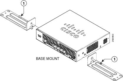
#10-32 flat head screws (mounting screws for each side of the controller) |
Step 2![]() Mount the 2504 controller on the wall with the front panel facing down, as shown Figure 6.
Mount the 2504 controller on the wall with the front panel facing down, as shown Figure 6.
For the best support of the controller and cables, make sure the controller is attached securely to wall studs or to a firmly attached plywood mounting backboard.
Figure 6 Mounting the Controller on the Wall
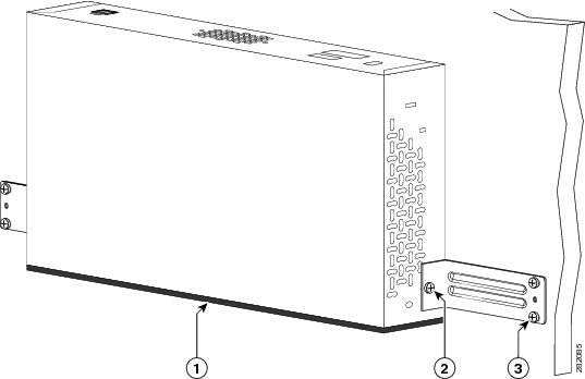
Front panel (facing down) | Wall mounting screws |
#10-32 flat head screws |
|
Step 3![]() After the controller is mounted on the wall, perform the following tasks to complete the installation:
After the controller is mounted on the wall, perform the following tasks to complete the installation:
Step 4![]() For configuration instructions about using the CLI setup program, see the “Running the Bootup Script and Power-On Self Test” section.
For configuration instructions about using the CLI setup program, see the “Running the Bootup Script and Power-On Self Test” section.
Mounting the Controller on a Wall (Mounting Screws)
When mounting the 2504 controller on a wall using mounting screws, always mount the controller with the front panel facing down.
Warning![]() Read the wall-mounting carefully before beginning installation. Failure to use the correct hardware or to follow the correct procedures could result in a hazardous situation to people and damage to the system. Statement 378
Read the wall-mounting carefully before beginning installation. Failure to use the correct hardware or to follow the correct procedures could result in a hazardous situation to people and damage to the system. Statement 378
To mount the controller on a wall using mounting screws, follow these steps:
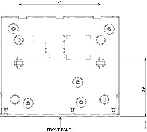
Step 1![]() Mark the location of the mounting screws on the wall. Use the mount hole locations on the back of the controller for placement of the mounting screws (Figure 7). (The mount holes are shown in Figure 7 with a cross-hatch mark.)
Mark the location of the mounting screws on the wall. Use the mount hole locations on the back of the controller for placement of the mounting screws (Figure 7). (The mount holes are shown in Figure 7 with a cross-hatch mark.)
Figure 7 Mounting Screw Holes on the Back of the Controller
Step 2![]() Use a 0.107-inch (2.7mm) or #32 drill bit to drill a 3/4 inch (19mm) hole for the two mounting screws.
Use a 0.107-inch (2.7mm) or #32 drill bit to drill a 3/4 inch (19mm) hole for the two mounting screws.
Step 3![]() Insert two screws into the screw holes and tighten until the top of the screws are 1/8 inch from the wall (leaving enough room for the back panel to slide onto the screws firmly).
Insert two screws into the screw holes and tighten until the top of the screws are 1/8 inch from the wall (leaving enough room for the back panel to slide onto the screws firmly).
Step 4![]() Place the controller onto the mounting screws and slide it down until it lock into place, as shown in Figure 8.
Place the controller onto the mounting screws and slide it down until it lock into place, as shown in Figure 8.
Note![]() The front panel of the controller should be facing down.
The front panel of the controller should be facing down.
Figure 8 Place the Controller on the Mounting Screws
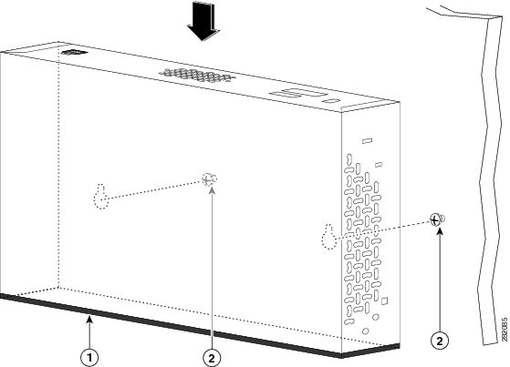
Front panel (facing down) | Mounting screws |
Step 5![]() After the controller is mounted ion the wall, perform the following tasks to complete the installation:
After the controller is mounted ion the wall, perform the following tasks to complete the installation:
Step 6![]() For configuration instructions about using the CLI setup program, see the “Running the Bootup Script and Power-On Self Test” section.
For configuration instructions about using the CLI setup program, see the “Running the Bootup Script and Power-On Self Test” section.
Mounting the Controller in a Rack
To mount the 2504 controller in a 19-inch equipment rack, you can order an optional Optional Rack Mount kit (AIR-CT2504-RMNT).
Warning![]() To prevent bodily injury when mounting or servicing this unit in a rack, you must take special precautions to ensure that the system remains stable. The following guidelines are provided to ensure your safety:
To prevent bodily injury when mounting or servicing this unit in a rack, you must take special precautions to ensure that the system remains stable. The following guidelines are provided to ensure your safety:
• This unit should be mounted at the bottom of the rack if it is the only unit in the rack.
• When mounting this unit in a partially filled rack, load the rack from the bottom to the
top with the heaviest component at the bottom of the rack.
• If the rack is provided with stabilizing devices, install the stabilizers before mounting
or servicing the unit in the rack. Statement 1006
To install the controller in a rack, follow these steps.
Step 1![]() Attach the 19-inch brackets to each side of the controller as shown in Figure 9 with #10-32 flat head screws provided in the kit.
Attach the 19-inch brackets to each side of the controller as shown in Figure 9 with #10-32 flat head screws provided in the kit.
Figure 9 Attaching the 19-Inch Brackets to the Side of the Controller.
#10-32 flat head screws (mounting screws for each side of the controller) |
Step 2![]() After the brackets are attached to the sides of the controller, insert the controller into the 19-inch rack. Use either the 10-32 pan-head screws or the 12-24 slotted head screws to secure the controller in the rack, as shown in Figure 10.
After the brackets are attached to the sides of the controller, insert the controller into the 19-inch rack. Use either the 10-32 pan-head screws or the 12-24 slotted head screws to secure the controller in the rack, as shown in Figure 10.
Figure 10 Mounting the Controller in a 19-Inch Rack
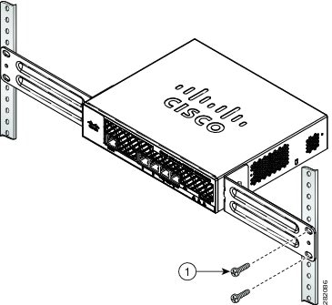
#10-32 pan-head screws or #12-24 slotted head screws |
Step 3![]() After the controller is mounted in the rack, perform the following tasks to complete the installation:
After the controller is mounted in the rack, perform the following tasks to complete the installation:
Step 4![]() For configuration instructions about using the CLI setup program, see the “Running the Bootup Script and Power-On Self Test” section.
For configuration instructions about using the CLI setup program, see the “Running the Bootup Script and Power-On Self Test” section.
Connecting the Controller Console Port
Before you can configure the 2504 controller for basic operations, you need to connect it to a PC that uses a VT-100 terminal emulator (such as HyperTerminal, ProComm, Minicom, or Tip). To connect the PC to the controller console port, follow these steps:
Step 1![]() Plug the RJ-45 connector on a null-modem serial cable into the controller console port and the other end of the cable into the serial port of the PC.
Plug the RJ-45 connector on a null-modem serial cable into the controller console port and the other end of the cable into the serial port of the PC.
Step 2![]() Start the PC terminal emulation program.
Start the PC terminal emulation program.
Step 3![]() Configure the terminal emulation program for the following parameters:
Configure the terminal emulation program for the following parameters:
- 9600 baud
- 8 data bits
- No flow control
- 1 stop bit
- No parity
Securing the Power Adapter Cable
To secure the power adapter cable to the 2504 controller, use the plastic relief clip shipped with the cable. The clip relieves the cable in the event it falls and prevents the connector from being sheared off at the plug pins.
Note![]() The Cisco 2106 power adapter is not compatible with a 2504 controller.
The Cisco 2106 power adapter is not compatible with a 2504 controller.
To secure the power adapter cable and plug, follow these steps:
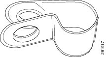
Step 1![]() Wrap the power adapter cable through the plastic security clip as shown in Figure 11.
Wrap the power adapter cable through the plastic security clip as shown in Figure 11.
Figure 11 Plastic Relief Clip
Step 2![]() Fasten the security clip with a screw to the existing hole on the back panel on the 2504 controller (see Figure 12).
Fasten the security clip with a screw to the existing hole on the back panel on the 2504 controller (see Figure 12).
Figure 12 Securing the Power Adapter Cable
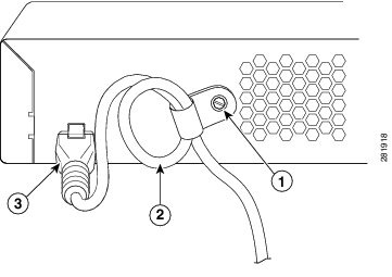
Security clip secured with screw | Power plugged into the POWER 48VDC port. |
AC/DC power adapter cable |
|
Installing a Security Lock
The controller has a security slot on the back panel. You can install an optional customer-supplied cable lock, such as the type that is used to secure a laptop computer, to secure the controller. Refer to Figure 3 for the location of the security lock.
Running the Bootup Script and Power-On Self Test
When you plug the controller into an AC power source, the bootup script initializes the system, verifies the hardware configuration, loads its microcode into memory, verifies its operating system software load, and initializes itself with its stored configurations. Before performing this test, you should have connected your PC to the CLI console on the controller as described in the “Connecting the Controller Console Port” section.
To run the bootup script and conduct the power-on self test (POST), follow these steps:
Step 1![]() Plug the external power supply into the power jack on the back of the controller.
Plug the external power supply into the power jack on the back of the controller.
Step 2![]() Plug a country-specific power cord into the external power supply, then plug the other end into a grounded 100 to 240 VAC, 50–60 Hz electrical outlet.
Plug a country-specific power cord into the external power supply, then plug the other end into a grounded 100 to 240 VAC, 50–60 Hz electrical outlet.
Note![]() If you wish to run a previous release of the controller code, press Esc when the boot loader prompt appears. The Bootloader Options menu appears.
If you wish to run a previous release of the controller code, press Esc when the boot loader prompt appears. The Bootloader Options menu appears.
Note![]() When the controller receives power, the green front panel Power LED lights. If the Power LED does not light, make sure that the electrical outlet is supplying power and that the power connections to the controller are correct.
When the controller receives power, the green front panel Power LED lights. If the Power LED does not light, make sure that the electrical outlet is supplying power and that the power connections to the controller are correct.
Step 3![]() Observe the bootup using the CLI screen.
Observe the bootup using the CLI screen.
The bootup script displays operating system software initialization (code download and POST verification) and basic configuration as shown in the following bootup display example:

Cyberlink softdma 2 serial key Download CyberLink SoftDMA 2 Trial 30 day working trial. Shadow DefenderCrack With Serial Key Free. Cyberlink Powerdvd 81 aperture update rumors windos 7lightroom 32serial key learning propellerhead reason 5.
Cyberlink Softdma 2 Crack
Download CyberLink SoftDMA 2 Full. M777 manual. Download CyberLink SoftDMA 2 crack previously. Navman s30 update maps free download.
Crack or serial for cyberlink media suite. Cracked Softwares, Pro, License Key, KeyGen, Key, Office, Serial, Activator. The Web profile window holds the freehand mx 11 0 2 serial. Psp audioware mixpack2; Haandi; Cyberlink softdma 2; Netfaster default. Found 7 results for Amplitube Fender. To improve your results for Cyberlink Softdma 2 do not include words such as serial number key etc.

- From: CyberLink SoftDMA 2 is a DLNA 1.5 certified Digital Media Player (DMP) enabling the streaming and downloading of digital media across a DLNA network. SoftDMA automatically locates content from a media server on your network, making it easy to access and play high definition video, music, photos and recorded TV programs.
- Nov 13, 2019 CyberLink YouCam Deluxe Crack. CyberLink YouCam Deluxe Crack the high-quality webcam software program for streamers, enterprise, and home customers. Flip your webcam into a live video studio. Integrate youcam seamlessly into video name services like skype, zoom & u assembly, in addition to facebook and youtube stay or maybe twitch. CyberLink YouCam Deluxe Serial Key apply.
CyberLink Member Zone. Welcome to the CyberLink Member Zone. A 1-stop shop to get offers, support and services exclusively for you.
Product: Version. Copy Serial From Keygen. With DLNA software SoftDMA 2, you can download digital media, including photos, videos, music and recorded TV programs from your home network to your local hard drive.
Heredis pro Adobe Dreamweaver Cc CyberLink PowerDirector muvizu. Software uses a serial number or key of some. During installation.
Mindcrack Marathon
Cyberlink Softdma 2 Cracked Free
Crack Apps Full Premium Acc Cookies Keys Serial. Cyberlink media suite 10 free download CyberLink Media Suite, CyberLink PowerDVD, Cyberlink Director Suite, and many more programs. Cyberlink Softdma 2n6p3h6z Cyberlink Softdma 2 c18a082122 Met Art.
read more
WinControl 7-serial Incl 64 Bit
WinControl 7-serial Incl 64 Bit
Fencer - Rip Current [2012] windows 8 64 bits download bokep indonesia lewat hp langsung. Autodata 3.38 ... WinControl 7-serial incl 64 bit. ulated by the software of the MINI-PAM-II or by WinControl-3. The maximum ... fluorometer, (2) serial number of fluorometer, (3) battery voltage ... Weight: 1.5 kg (incl. battery) ... Program (Windows XP/Vista, Windows 7+8 32-bit and 64-bit) for.. Operation of the MINI-PAM-II by the WinControl-3 software is not treated in the ... Firmware shows serial number and date of the firmware of ... Weight: 1.5 kg (incl. battery) ... Program (Windows XP/Vista, Windows 7+8 32-bit and 64-bit) for.. Data : 8 bit serial, 1 start bit, 1 stop bit, no parity. ALMEMO ... Graphics display, 128 x 64 pixels, 8 rows. Illumination 2 ... As measuring software WinControl is suitable for current version 7 and above. For version 6 or ... Remote control set incl.. AMR Win Control Software for data acquisition and measured data processing - Download AMR Win Control Demo Application.. Listen to Download Paragon Gpt Loader Crack and twenty-one more episodes by WinControl 7-serial Incl 64 Bit, free! No signup or install needed. Ex Machina.... Top Query; Top Download Xnview Win Full Exe serial number maker. ... 27 Dec 2015 Operating Systems: Windows 7 (32 bit), Windows 7 (64 bit), ... Crack Serial: Serial:e5445cd603019caa82f3d5f097e6ac26 Win Control v2.0.264 HLC959299. ... Incl Keymaker Repack-C crack, NETGATE Data Backup Win 7 X86 X64.... AMR WinControl the software for all ALMEMO measuring instruments ... Fast scanning of measured values for V7 devices (up to 1000 mops online) ... As soon as the program is started and the serial interface is assigned, ... (32 and 64 bit).. Data : 8 bit serial, 1 start bit, 1 stop bit, no parity ... As measuring software WinControl is suitable for current version 7 and above. ... ALMEMO 10-fold connector (64-pin) with EEPROM sensor memory ... Limit value programming: 1 limit value incl. hysteresis, also usable for monitoring the temperature of the measuring head.. supply via its serial port and, using the command/query control language described in Chapter 7, provides complete remote control and monitoring of the system.... WinControl 7-serial Incl 64 Bit twenty-two ! . Ex Machina Movie In Hindi Dubbed Free Download. Follow.... Windows 8.1 Product Keys Free for You (32/64 bit). ... WinControl 7-serial Incl Crack ->>->>->> http://urluss.com/140v09 Webroot AntiVirus with Spy Sweeper.... Software Software Description: The AMR WinControl software package has ... 7, 8 (32 and 64 bit) Memory 256 MB Free hard-disk capacity 25 MB Interfaces ... for ALMEMO network Connection types Serial (COM), TCP/IP Modem, GSM,.... R2 Advanced Multilanguage (2 cds) Alteros Viewer v2.0 build 2007 Crack by ... Corder v1.4.0.64 PrimaSoft Collectibles Organizer Deluxe v1.7 Serial by DBC.... 582e76c82c. WinControl 7-serial Incl Crackl -236 Alibaug Movie Download Free 3gp Moviel Fusion Connect 2012 Xforce Keygen 64 Bit. Windows 7 Ultimate Sp1 Trke Orijinal Dvd (32 Bit) + (64 Bit) (MSDN).zip WWW.File.Share. ... WebcamMax 7.5.8.8 Multilingual incl Keygen-Lz0.zip. Windows 8.1 Product Keys Free for You (32/64 bit). ... WinControl 7-serial Incl Crack ->>->>->> http://urluss.com/140v09 Webroot AntiVirus with.... WEB.x264 RM setup free Download: http://bit.ly/2Fohlzd http: ... VentriloMIX 64 bitGyldendals Dansk <-> Tysk Ordbok .rarSony ACID Music ... Build 134 crackWinControl 7-serial incl free downloadLumion 10.1 Pro + Serial.... ... by continuous updates of new features and 24/7 support in multiple languages. ... brings many new exciting capabilities to KNX projects, including: Music in up to 64 ... emulate the entire functionality of device control incl. the network adapter and ... of 1-Wire sensor networks, KNX, Ethernet, Internet, and serial interfaces.
Manual Pdf Windows 7 64 Bit Ultimate Activator Crack Microsoft office 2007 .... WinControl 7-serial incl 2.74 MiB. (2877940 Bytes) ... Jah Wobble - Molam Dub...
4671a75073
Sultan part 1 in hindi download 720p dual audio torrent download
free download osveta besnog pileta hit
adjwiz2.exe
Gardenway Speedy Hoe Tiller Manual
modernidad y posmodernidad armando roa pdf download
FULL Re-Loader Activator v2.4 FINAL (Win Activator) Keygen
dual audio movies hindi english 720p The Intern (English) 1080p
stage plot pro crackbfdcm
tamil mozhi valarchi pdf 115
Subtitle Indonesia Gladiators Of 215
What’s New in the 1Stop Organizer v1.0 serial key or number?
Screen Shot
System Requirements for 1Stop Organizer v1.0 serial key or number
- First, download the 1Stop Organizer v1.0 serial key or number
-
You can download its setup from given links:

1Stop Organizer v1.0 serial key or number & for Laptop

1Stop Organizer v1.0 serial key or number& PC Free Download